When the AC voltage is applied to the capacitor, it causes the phase difference between the voltage and current, which can be used to filter or tune the circuit. However, when the inductor is connected to the AC voltage it resists the change in the current, thus causing the phase difference between the voltage and current.
Outline:
- Resistance in AC Circuit
- Impedance in AC Circuit
- Impedance in RL Circuit
- Example
- Impedance in RC Circuit
- Example
- Impedance in RLC circuit
- Series RLC Circuit
- Example
- Parallel RLC Circuit
- Example
- Conclusion
Resistance in AC Circuit
Resistors are passive devices that solemnly restrict the flow of the current by dissipating heat and do not require energy to operate. Unlike DC circuits, the ratio of current and voltage depends on the frequency of the supply, the phase angle, or the phase difference. The value of the resistance remains the same even if the values for the current and voltage are varying, unlike the inductors and capacitors. Below is a simple AC circuit having a resistance connected with the source:
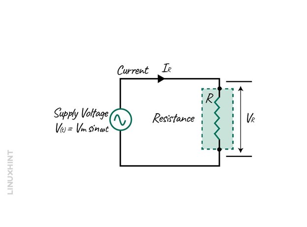
The instantaneous supply voltage across the resistor R is equal to the supply voltage, and the equation for it is:

The equation for finding the current through the resistor is:

Now putting the value for VR in the above equation, we get:

Now the instantaneous current will be:
![]()
As the voltage is the product of current and resistance, then the instantaneous voltage across the resistor will be:
![]()
The direction of the current flowing through the resistor in AC circuits has no effect on the resistor, and the same is the case with the varying values of current and voltage. Due to this, the current and voltage are in phase and rise and fall simultaneously:
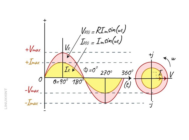
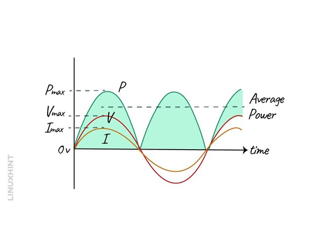
Since the voltage and current are in phase, the phase angle will be zero, which means that the power factor will be 1. Moreover, the power can be calculated by multiplying the voltage and current, whose resultant will remain positive even in the negative half cycle.
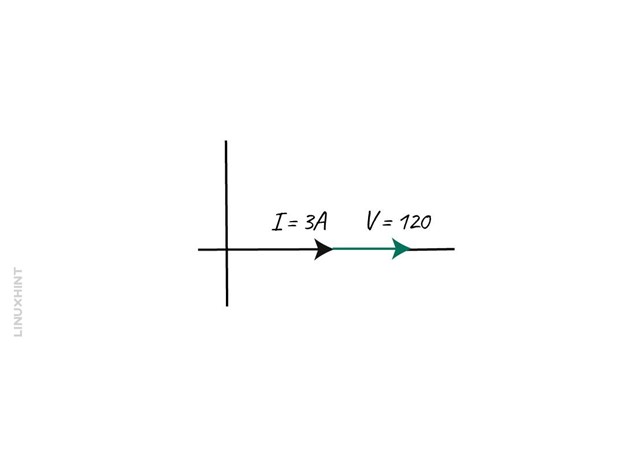
Example 1: Calculating the Resistance in an AC circuit
Consider an AC circuit having a voltage of 120 Volts and a current of 3 Amps, then find the resistance:
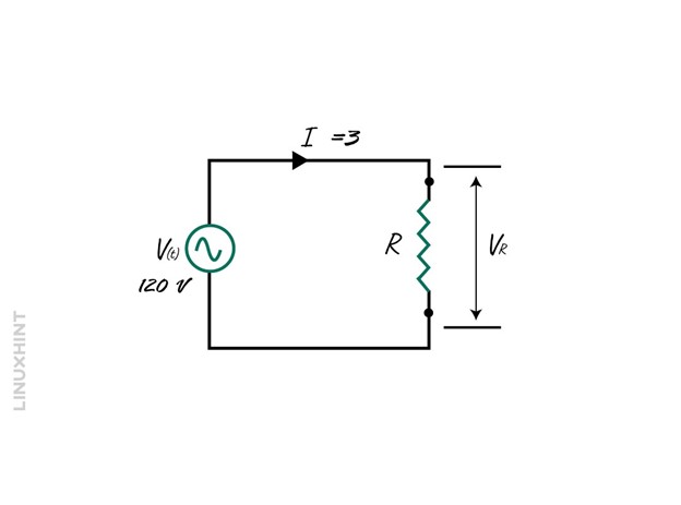
To calculate the resistance, just place the values in Ohm’s law formula:

Since there is no phase difference, the phaser diagram will be:
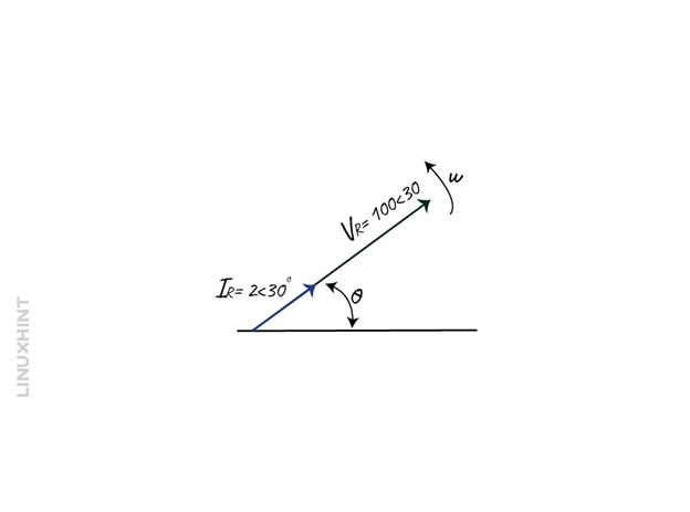
Example 2: Calculating the Current of AC Resistive Circuit
Consider an AC circuit having a sinusoidal voltage of V(t) = 100 cos(ωt + 30) and a resistance of 50 Ohms. Find its maximum peak current value.
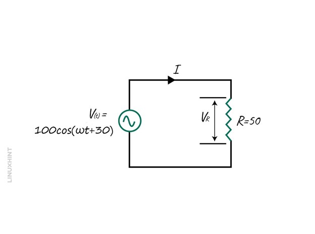
The voltage equation can be further simplified:
![]()
Now finding the current using Ohm’s law:

So, the phaser diagram for the voltage and current will be:
Impedance in AC Circuit
In an AC circuit when an inductor and a capacitor are connected along with the resistance (RLC), the total resistance is referred to as impedance. However, the circuits do not always have these three components, as the circuit can consist of a resistor and capacitor (RC) or resistor and an inductor (RL). To find out the impedance of all these three circuit configurations, there are slight differences in the formulas.
Impedance in RL Circuit
When an inductor is connected to a voltage source, a magnetic field is created around it, in which it stores the energy. In AC circuits, the opposition to the current flowing through the inductor depends on the frequency of the supply voltage and the inductance of the coil. So, like the resistance of the resistor, the inductor has inductive reactance whose equation is:
![]()
Here is a simple circuit that is purely inductive, having a sinusoidal voltage:
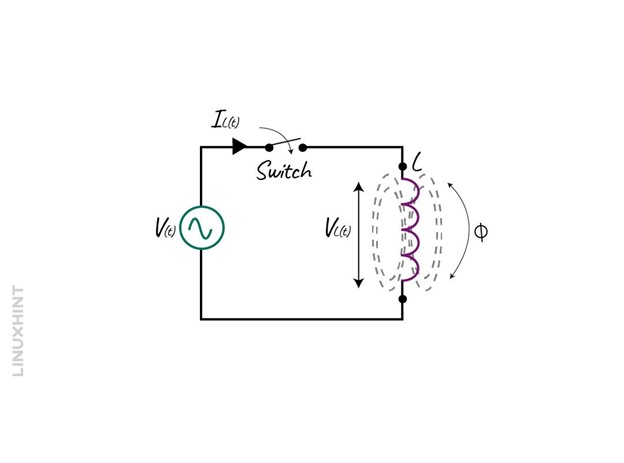
Now when the switch is closed the magnetic field will be produced which will oppose the flow of the current. Thus, due to such opposition, the voltage will lead, and the current will lag as when the polarity is changed the delay will increase up to 90 degrees.
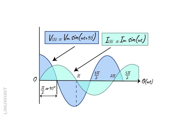
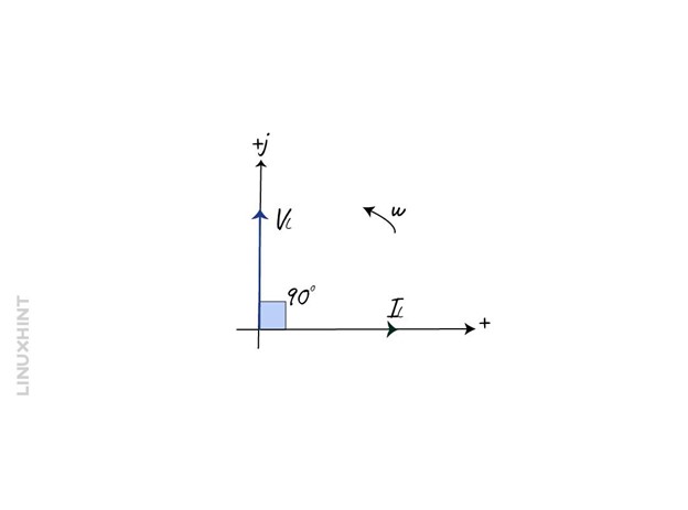
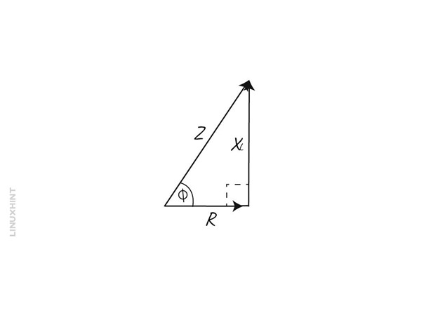
So, in other words the current lags the voltage by 90 degrees in the inductive circuits and the phaser diagram for an inductive circuit will be:
Now if in the circuit a resistance is connected, then the vector diagram and the phaser diagram will be:
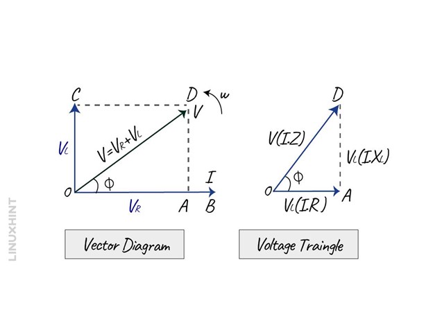
Here, in the vector diagram, OA is the voltage across the resistive element, there is no phase difference between its voltage and current. The OC on the other hand is the voltage that has a phase angle difference of 90 degrees, and OD is the resultant voltage. So, the final triangle will be OAD as the voltage leads by 90 degrees and from that the total voltage using the Pythagoras theorem will be:
![]()
Now taking the square root on both sides of the equation, we get:

Now placing the values for voltage using the Ohm’s law:
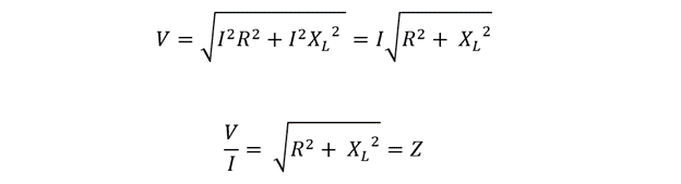
Now the formula impedance Z will:

So, the Impedance is the combination of both the resistance and the reactance and has the unit of Ohms. Impedance in the complex form can be written as:
![]()
So, if each side of the voltage triangle is divided by current, then the sides represent resistance, inductance, and reactance:
So, we can write the Pythagoras theorem as:
![]()
Example: Inductance of RL Circuit
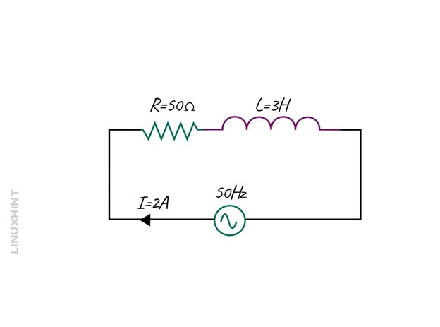
Consider an RL series circuit having a sinusoidal voltage with an inductance of 3 H and a resistance of 50 Ohms. The current flowing through the circuit is 2 Amps and the frequency of the voltage is 50Hz.
To find the impedance of the circuit first, the inductive reactance is to be found so:
![]()
Now placing the values of frequency and inductance, we get:
![]()
Now using the impedance formula for calculating the impedance:

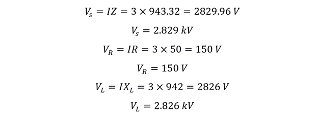
Since in series, the current through all the components remains the same, it is the voltage that differs, so now calculating the voltage across each component:
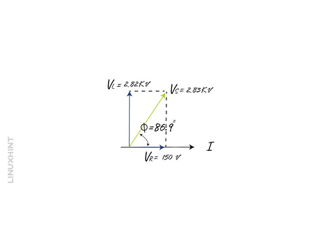
Now the phase angle can be calculated as:

So, the phaser diagram will be:
Impedance in RC Circuit
When a capacitor is connected in series with the resistance, it is referred to as an RC circuit. When the sinusoidal voltage is applied to the capacitor, it begins to charge and in the negative half cycle, the direction will be opposite. It is to be noted that in an AC circuit the capacitor charges and discharges constantly, but the rate of charge and discharge mainly depends on the frequency. Consider a circuit having a capacitor connected to an AC source:
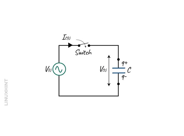
When the switch is in the ON state the voltage begins to rise in the positive direction at the maximum rate as it crosses the zero reference with respect to the time given which is 0 degrees. Once the rate of change of potential difference is at maximum, the number of electrons moving between the plates will also be maximum. Now, when the voltage wave reaches 90 degrees, its rate of increase begins to slow down and eventually becomes zero for a while. So, this is the instant at which the capacitor is fully charged and there is no current flowing into the capacitor. The voltage now will start to decrease in the negative direction, and the wave reaches the reference signal of 180 degrees.
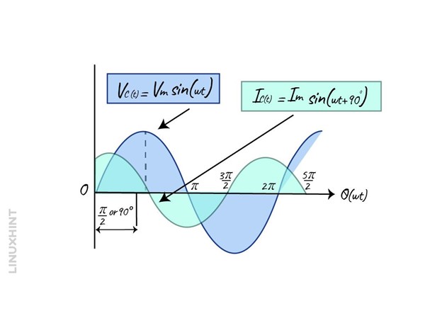
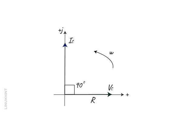
In the negative half cycle that is 180 degrees to 360 degrees, the voltage direction is opposite and reaches the negative peak value at 270 degrees. From the above waveform, it can be seen that in the capacitive circuit, the current leads the voltage by 90 degrees and the phaser diagram will be:
The impedance in the case of the capacitor is the capacitive reactance, which can be calculated using the below equation:

Now in case of the RC circuit the impedance of the circuit will include both the capacitive reactance and resistance:
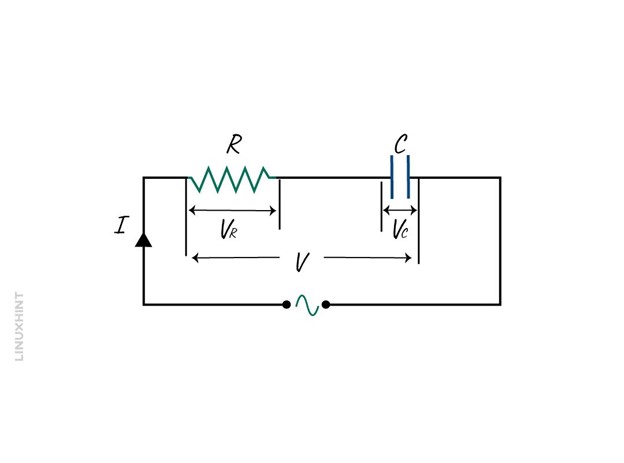
In a resistor, both the voltage and current are in phase and in the capacitor as mentioned above is that the voltage lags the current by 90 degrees so the resultant vector diagram and voltage triangle will be:
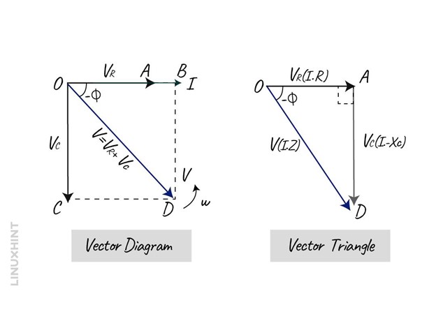
Here on the vector diagram the OB is the current reference and the OA is the voltage reference line across the resistive component. The OC line shows the voltage across the capacitor that lags the current by 90 degrees, the line OD gives the resultant voltage.
So, the final triangle will be OAD as the voltage lags by 90 degrees and form that the total voltage using the Pythagoras theorem will be:

Now taking the square root on both sides of the equation, we get:

Now placing the values for voltage using the Ohms law:

Now the formula impedance Z will:

So, the combination of both the resistance and the reactance is referred to as impedance, it has the unit of Ohms. Impedance in the complex form can be written as:
![]()
Example: Calculate the Impedance of RC Circuit
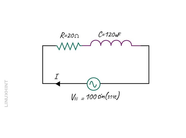
Consider an RC circuit having a Resistance of 20 Ohms and capacitance of 120µF connected with a sinusoidal voltage:
To find the impedance of the circuit first the inductive reactance is to be found so for that:

Now use the impedance formula for calculating the impedance:

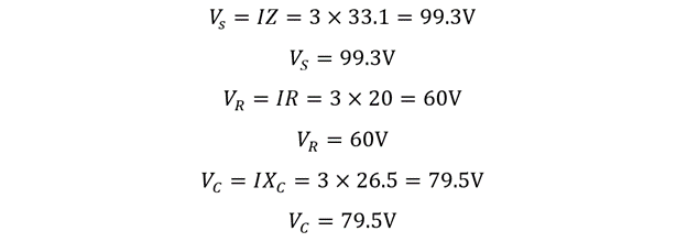
To find the current in the circuit, simply use Ohm’s law:

Since in series, current through all the components remains the same, it is the voltage that differs, so now calculating the voltage across each component:
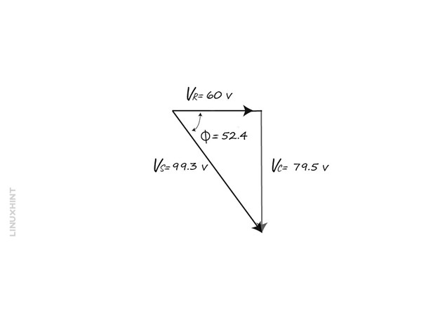
Now the phase angle can be calculated as:

The angle between the voltage and current will 45 degrees, so the voltage triangle will be:
Impedance in RLC Circuit
The RLC circuit consists of a resistor, inductor, and capacitor. It can be in two configurations, one in series and the other in parallel. The waveform of the pure resistor is in phase, for pure inductor current lags the voltage by 90 degrees, and for capacitor current leads the voltage by 90 degrees. The phase difference normally depends on the component’s reactive values in the circuit. In the case of the resistance, the reactive component is zero, for the inductor it is positive, and for the capacitor it is negative.
Series RLC Circuit
The series circuit has a single loop and the same amount of current flows through each of the circuit components, below is a basic RLC series configuration:
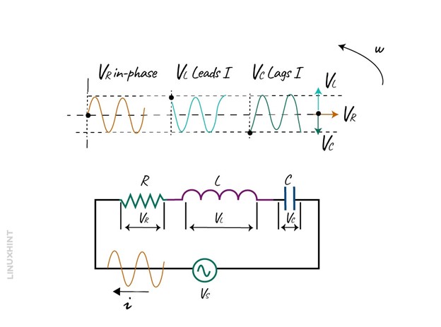
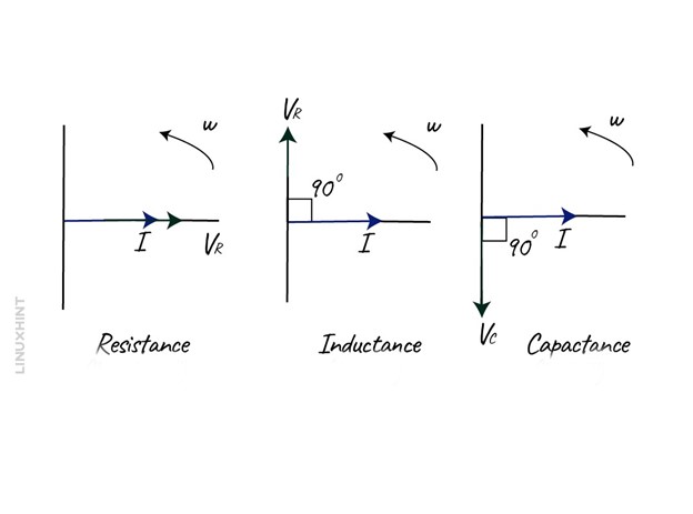
The voltage across each of the components will be different, so the amplitude of the source voltage will depend on the individual voltages across the components. The vector diagrams for each of the components are shown below:
To draw the phaser diagram of the RLC circuit, combine all three phasers and add the voltages vertically. Since in series the current flowing is common to all the components, it can be taken as a reference, and a vector of voltages can be drawn using their respective angles:
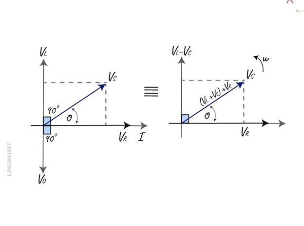
The resulting vectors VS is obtained by summing up the vectors for the inductor, capacitor voltages together and then adding the vector for the resistor. So now using the Pythagoras theorem we can write:
![]()
In the above equation, it must be kept in mind that the final reactive voltage is positive so the expression (VL-VC) can also be written as (VC-VL), The values for the voltage for resistor, inductor, and the capacitor is:

So now if we put the values of voltages in the Pythagorean theorem, we get:

As from the Ohm’s law the product of current and resistance results in voltage, so the impedance on a series RLC circuit will be:
![]()
The equation for the impedance can be further written as:

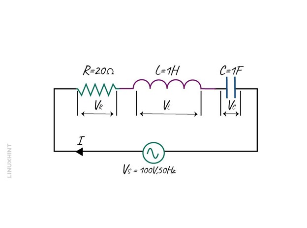
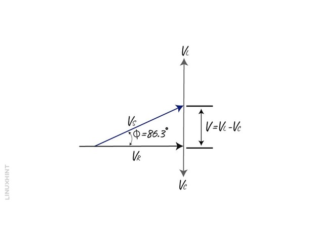
Example: Calculating the Impedance of Series RLC Circuit
Consider an RLC circuit having a resistance of 20 Ohms, inductance of 1H and capacitance of 1F. Find the total impedance of the AC circuit provided in the voltage and frequency of 100 V and 50 Hz.
First, calculate the inductive reactance and capacitive reactance:

Now calculate the total impedance of the circuit:

To find out the phase angle:

So the angle between the voltage and current is 86.3 degrees, and the phaser diagram will be:
Parallel RLC Circuit
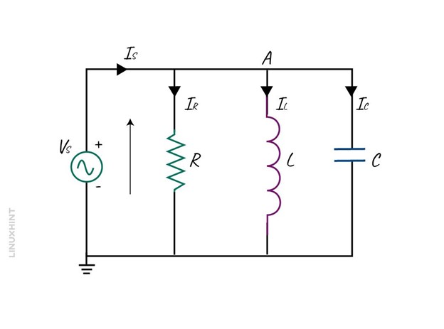
In a parallel RLC circuit instead of current, the voltage is now common and the current for each component is different, below is the basic configuration of an RLC circuit in the parallel configuration:
Now, by keeping the voltage as a reference, all the three current vectors can be drawn to create a phaser diagram. The resulting vector is the addition of two vectors IL and IC and the summing up the result with the third vector IR.
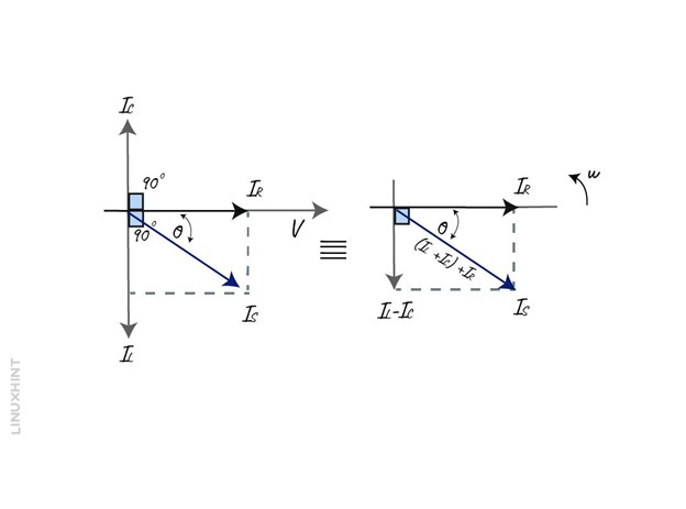
Now using the Pythagoras theorem, the equation for the resultant can be written as:

Now, putting the value of current using Ohm’s law:

To find the impedance of the RLC parallel circuit, the Ohm’s law can be written as:

Example: Calculating the Impedance of Parallel RLC Circuit
Consider an RLC circuit having a resistance of 100 Ohms and the inductance of 1H, find the total impedance of the circuit given that the capacitance of the circuit is 1F and the frequency of the supply is 60Hz:
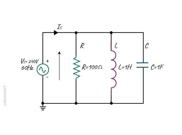
First, calculate the inductive reactance and capacitive reactance:

Now, placing the value of reactance in the impedance formula for the RLC circuit:
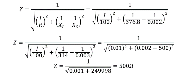
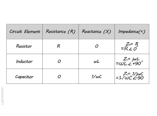
The impedance of the parallel RLC circuit is 500 Ohms and, to sum up, the reactance of each component in the RLC circuit is given in the table below:
Conclusion
An AC circuit can be purely resistive, inductive, capacitive, and a mix of all these components. The impedance of an AC circuit is the summation of the resistance of these components. In the case of resistance, there is no reactance, and the phase difference is zero, whereas in the case of inductance, the voltage will lead by 90 degrees. In the case of capacitance, the current will lead by 90 degrees.