Active High Pass Filter
The filter that only passes the high-frequency signal but stops the low-frequency signal is known as an active high-pass filter. The gain achieved by the active high pass filter is more than unity. The below given figure below is a prototype of a high-pass filter. Clear amplification of the signal is shown in the figure by the filter. its frequency response is the same as that of the passive filter. The amplitude is different in both active and passive filters.
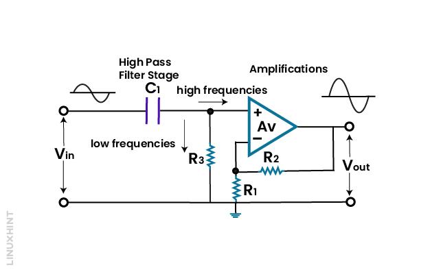
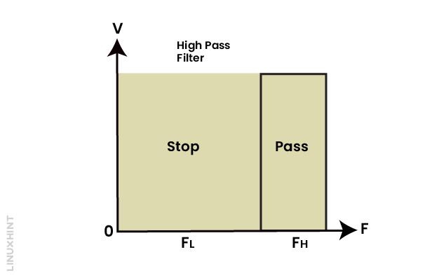
The characteristics of active high pass filter is depicted below, FL is the low pass frequency, and FH is the high pass frequency:
Gain output of Active High Pass Filter
The voltage gain of the active high pass filter is given by the equation is represented as
Where:
Af represents the bandpass gain of the filter:
f= is the input signal frequency
fc= is the cut-off frequency
The performance of the active high pass filter is proven by frequency gain equations:
1: For low pass f<fc
2: On cut-off frequency f=fc:
3: For high frequency f>fc :
Af improves from zero to the low frequency when f=fc the gain is 0.707. After cut-off frequency fc all frequencies are band pass, so this filter is known as a high pass filter.
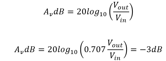
Generally, the gain is represented in dB when dealing with the magnitude of the band pass gain, so it is given as
The frequency response curve of first order filter is 20dB/decade and 6dB/octave to find the cut off frequency which is always -3dB.
The corner frequency (fc) is found out by the formula:
The phase angle of active high pass filter is given by:
Second Order High Pass Filter
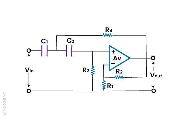
The second order high pass filter is obtained by just adding an RC network to the input of the circuit. The frequency response is like the first order high pass filter, but the stop band roll off at 40dB/decade.
Cut-off frequency of this second order high pass filter is given as:
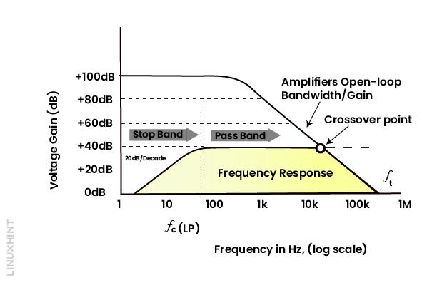
Frequency Response Curve
The open loop characteristic of an op-amp plays an important role in the frequency response of this filter by limiting the passband frequency. The wide band response of this filter will appear due to the quality of the operational amplifier. The accuracy of the high pass filter will be increased due to the operational amplifier.
Example of Second Order High Pass Filter
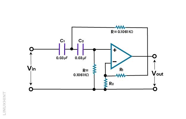
The cut-off frequency is 5 kHz, the delay rate is given as 40dB/decade, this delay rate clearly shows that it is a second order filter. The values of capacitor C1=C2=0.03F:
The cut-off frequency is given by
Now by putting the values in the formula, find the value of R:
Suppose the gain is:
So:
Thus:
The overall filter circuit is shown below:
Conclusion
The active high pass filter circuit passes the higher frequency signal and stops the lower frequencies signal. The order of these filters is not fixed to the first and second order, it is increased as its size increases. The accuracy of the filter depends on the order of the filter.

