The pulse width modulation technique modifies the width of DC input signals resulting in varying magnitudes of input voltages and power at the outputs. This technique is quite useful in controlling the amount of power and voltage being delivered to the output circuit. This article describes speed control of DC motors using pulse-width modulation techniques.
What is Pulse Width Modulation (PWM)
Pulse width modulation is a technique of varying voltage or power magnitudes from a DC source to look like an AC signal at a load. Pulse width modulation is used to power AC loads from DC sources. PWM varies power and voltage being supplied from 0 to 100% magnitudes to the load which resembles AC waveforms. PWM is also called the duty cycle variation technique.
Pulse Width Modulation (PWM) for DC Motors
Pulse-width modulation (PWM) is also called the duty-cycle variation technique. It is frequently used in the regulation of DC motor speeds. The duty cycle refers to the proportion of time during a pulse-width modulation (PWM) period that the digital signal is in a “high” state, relative to the combined duration of the ‘’low’’ and ‘’high’’ states. The below figure illustrates the 5V pulses exhibiting duty cycles ranging from 0% to 50%.
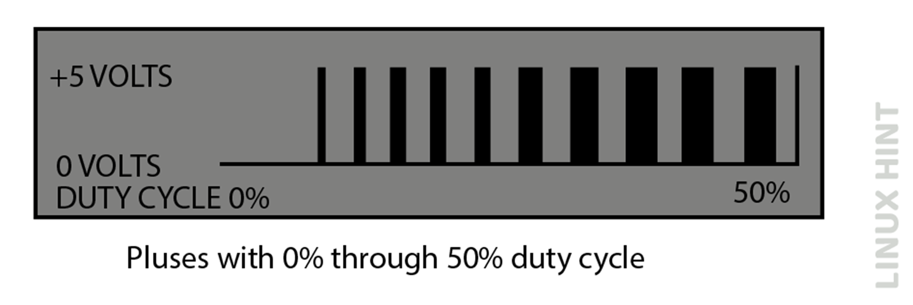
The mean direct current (DC) voltage for a duty cycle of 0% is determined to be zero. Conversely, when the duty cycle is 25%, the average voltage is calculated to be 1.25V, which corresponds to 25% of the total voltage of 5V. When the duty cycle is shifted to a 50% value, the average voltage is measured to be 2.5V. Similarly, when the duty cycle is increased to 75%, the average voltage is found to be 3.75V.
The maximum duty cycle attainable is 100%, representing a direct current (DC) waveform. By manipulating the pulse width, the average voltage across a direct current (DC) motor can be adjusted, resulting in a corresponding change in its rotational speed.
How to Control Speed of a DC Motor using Pulse Width Modulation (PWM) Technique
The below circuit illustrates the utilization of the Pulse Width Modulation (PWM) technique for the purpose of controlling the speed of a Direct Current (DC) motor:
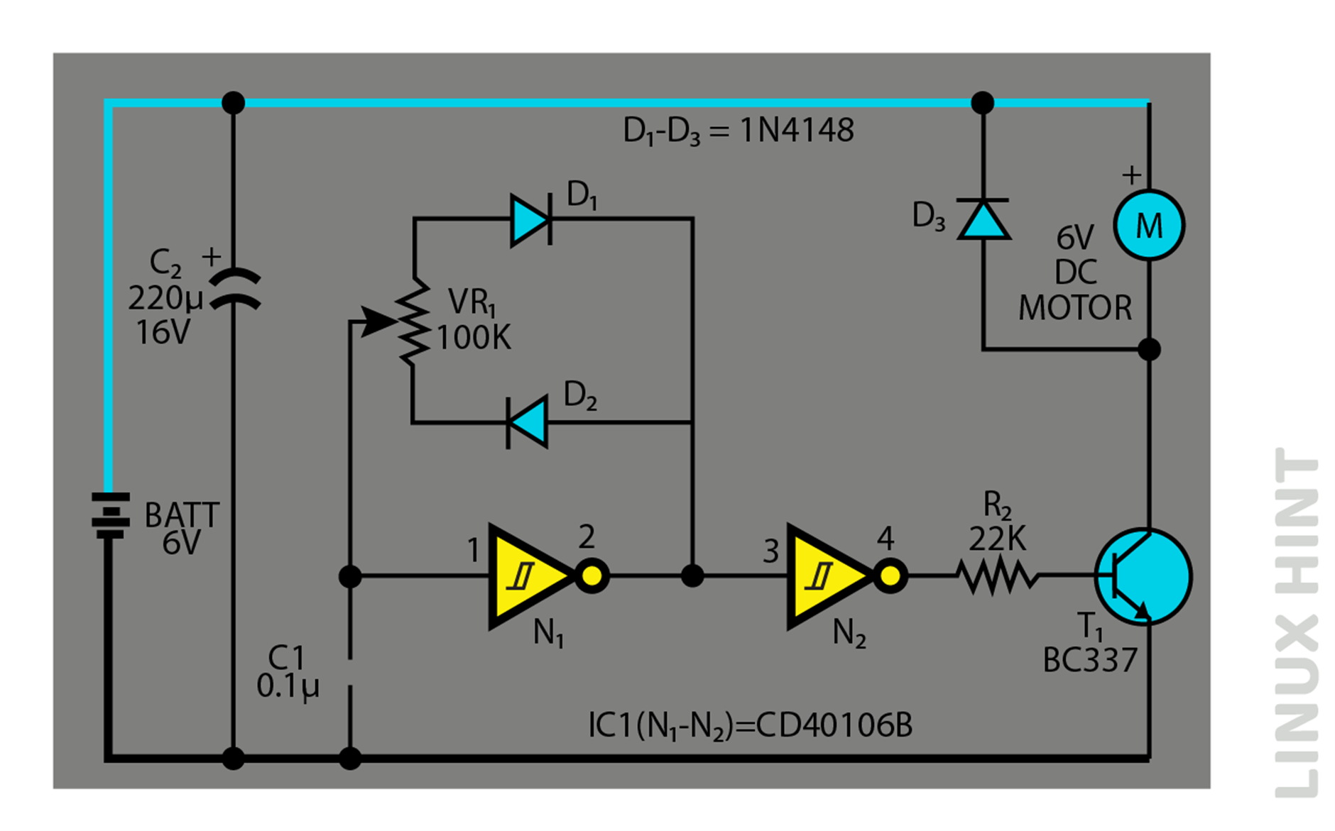
The N1 inverting Schmitt trigger is set up as an astable multivibrator, exhibiting a consistent period while allowing for a variable duty cycle. The overall resistance within the circuit, VR1, is measured at 100 kilo-ohms during a full cycle. However, the specific portion of VR1 utilized during the positive and negative parts of each cycle may be adjusted by manipulating the position of its wiper contact.
This adjustment allows for the modification of the pulse width, resulting in a changeable output. The Schmitt gate N2 functions as a buffer/driver, specifically designed to amplify and drive the transistor T1 when there are positive signals at its base. Hence, it can be observed that the mean magnitude of direct current (DC) driving pulses, or the velocity of motor M, exhibits a direct relationship with the adjustment of the wiper position of the VR1 potentiometer. Capacitor C2 functions as a reservoir capacitor, ensuring a consistent voltage supply to the circuit.
Therefore, by adjusting the variable resistor VR1, it is possible to modify the duty cycle within the range of 0% to 100% and consequently control the speed of the motor from a state of complete cessation to maximum velocity smoothly and uninterruptedly. The diodes effectively alter the timing resistor values during the processes of both charging as well as discharging the timing capacitor C1.
Pulse Period & Frequency
The equation provided approximates the duration of the pulse or rest period. The duration of the pulse or rest period can be approximated as 0.4 times the product of C1 (measured in Farads) and VR1 (measured in ohms).

The frequency will remain constant. The frequency can be approximated as 2.466 divided by the product of VR1 and C1, which can be determined using the following equation:

In our circuit, recommended values have been used as VR1=50 kilo ohms, C1=0.1µF:

Conclusion
Pulse width modulation used a duty cycle variation technique of input DC voltage from values of 0 to 100%. The change in DC voltages across the DC motor varies its operational speed and therefore PWM technique can directly control the speed of DC motors.