Diode Clipping Circuits
Diode clipping circuits are electronic circuits that use diodes to limit or control the amplitude of an electrical signal. These are electrical circuits that contain one or more diodes that trim the input signals. The output depends on both the direction of the diode and the input signals. In the circuit below, a diode facing downwards is connected in series with resistor R1 for limiting the positive half of the input signal.
Working Principle and Classifications
The working principle is basically the operation of diodes in the circuit. The diode does not conduct at voltages lower than the cut-off value of 0.7V. As soon as the cut-off voltage is exceeded, the current starts flowing, and the voltage drop remains at the same value. In reverse biased condition, the diode acts like an open circuit and any input signal cannot pass through the diode in this condition and is reflected at the output bypassing the diode connected in parallel arrangement. The clipping of voltages can be of different types. These are discussed below:
- Positive Diode Clipper
- Negative Diode Clipper
- Positive and Negative Diode Clipper
- Positive Bias Diode Clipper
- Negative Bias Diode Clipper
- Positive and Negative Bias Clipper
- Zener Diode Clipper
- Zener Diode Full Wave Clipper
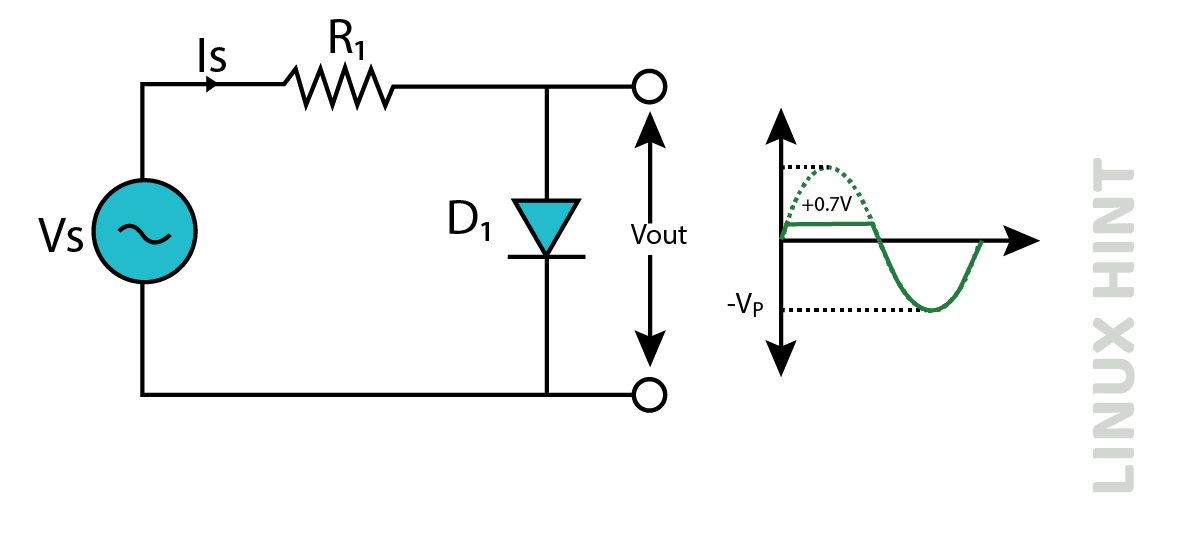
Positive Diode Clippers
A positive diode clipping circuit selectively cuts off the positive half of the input AC signal. A positive diode trimmer circuit selectively limits the positive half-cycles of an input signal, allowing the portion above a certain threshold to pass while attenuating the rest of the signal.
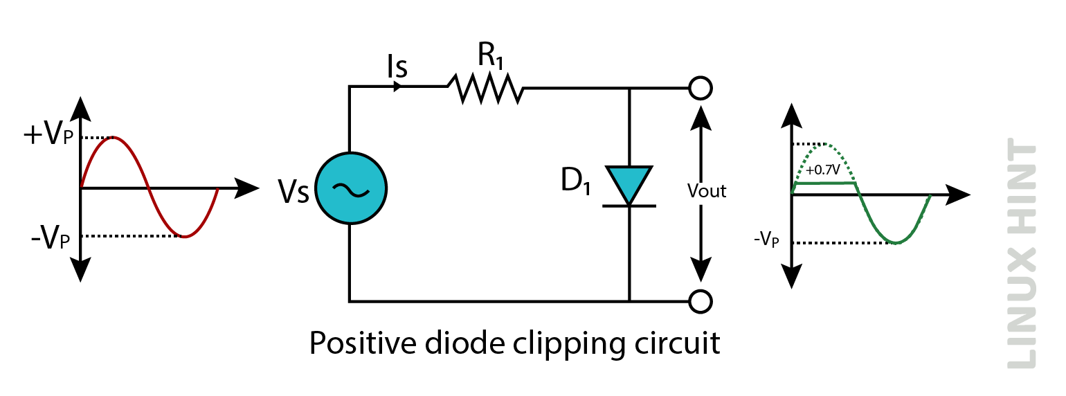
The diode remains off until the positive half-cycle voltage exceeds about 0.7V. After the diode enters the conducting state, regardless of the input voltage, a forward voltage drop is maintained across the diode. The positive half-cycle shape of the output waveform appears to be flat. In the negative half cycle, the diode remains in reverse bias condition and acts like an open circuit. As a result, the entire signal input appears at the diode. This circuit only attenuates the input signal during positive half cycles. Any voltage above +0.7V will be cut off.
Negative Diode Clippers
Negative diode clipping is a process in which a diode is used to limit the signal amplitude by removing or clipping a portion of the signal.
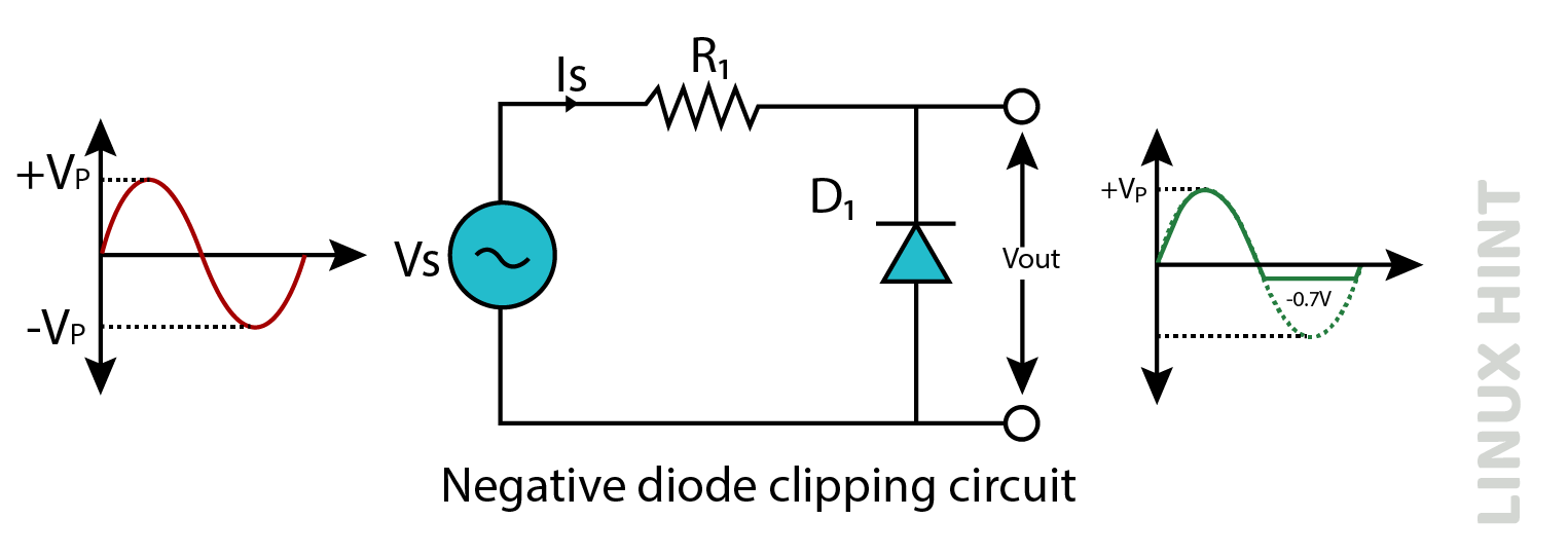
The Negative clipping circuit trim voltages during negative half cycles. The operation mechanism is similar to the positive diode cut-off circuit, except that the diode bias is reversed. The negative voltage is limited to -0.7V by the negative cutoff circuit. Any voltage value that falls below this threshold will be attenuated.
Positive & Negative Diode Clippers
Positive and negative circuit clips are circuit components that can limit or control the amplitude of an electrical signal by allowing only certain positive or negative currents to pass while reducing or suppressing the rest.
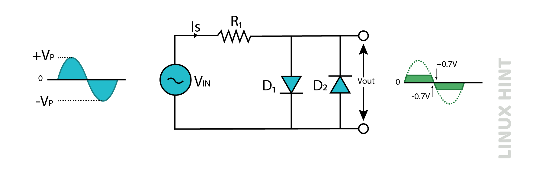
The combination of positive and negative clipping circuits results in an integrated clipping circuit that effectively limits the voltage amplitude in the positive and negative circuits. Diodes are arranged in an antiparallel configuration, one conducting and the other non-conducting. In the positive half-cycle, diode D1 switches ON and conducts and D2 switches off or remains open. During negative circulation, the opposite process occurs. The positive half-cycles of the output waveform show a maximum amplitude of +0.7V while the negative half-cycles show a minimum amplitude of -0.7V.
Positive Bias Diode Clipper
A positive cycle bias diode clipper clips the amplitude of positive voltage cycles in an electrical signal. The arrangement is illustrated below:
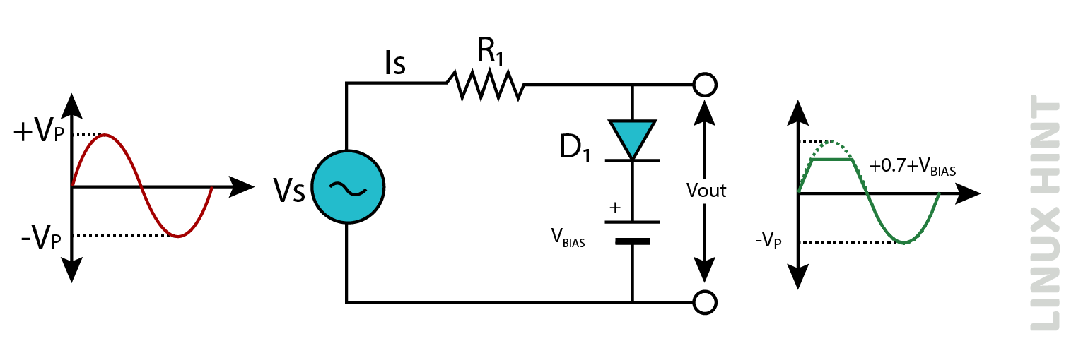
The purpose of the above circuit is to limit the voltage above +0.7+VBIAS. A positive cycle bias diode chopper is a circuit element that selectively limits the amplitude of the positive half cycles of the input signal.
The forward voltage drop only limits the voltage limit set by the diode trim circuits. The bias voltage is used in series with the diode to increase the starting voltage. The cathode of the diode is held at zero potential, but a voltage of +0.7V is required to produce a forward bias on the anode. Therefore, the forward bias condition requires a voltage of +0.7+VBIAS.
Negative Bias Diode Clipper
A negative bias diode chopper is a common circuit configuration used to limit the amplitude of an input signal in electronic systems.
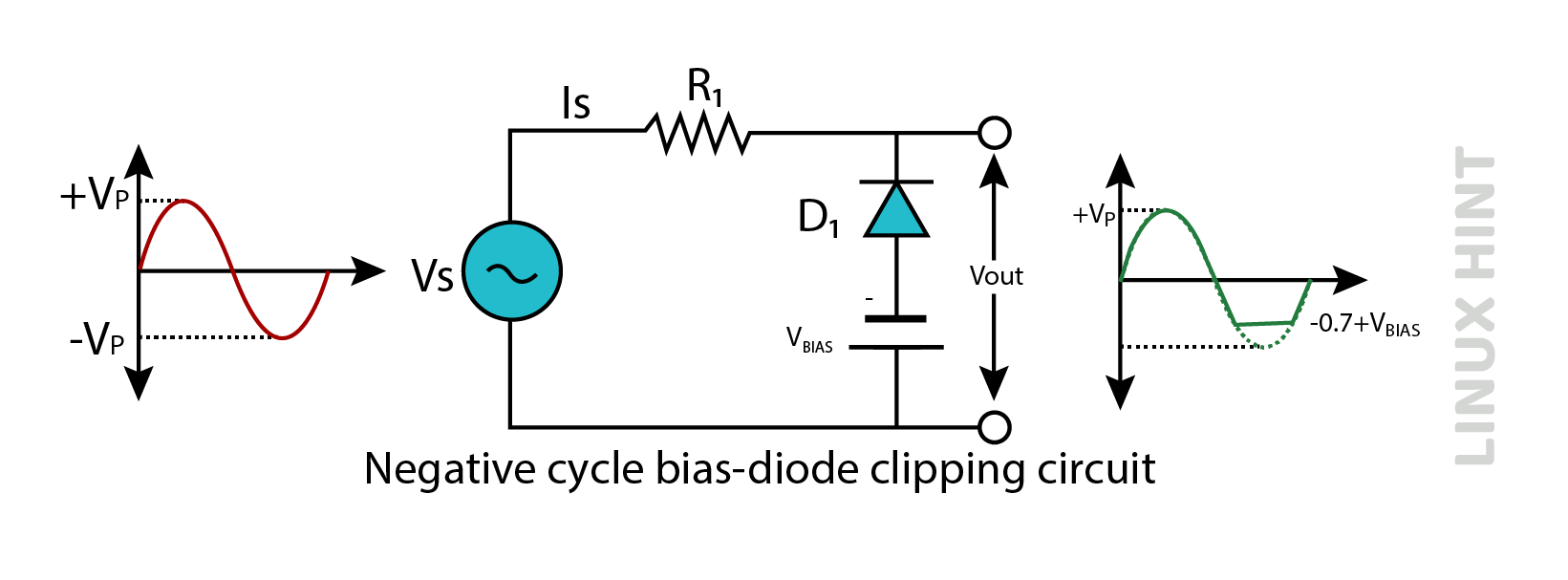
A reverse-polarity voltage applied in series with the diode is similar to the cutoff of a positive-biased diode. The clipping process makes it easy to apply reverse bias to the diode, but the diode requires a higher voltage to forward bias than if it were unbiased. This circuit limits voltages below -0.7-VBIAS.
Positive and Negative Bias Clippers
Biased positive and negative diodes are used to effectively reduce both positive and negative halves. The bias voltage on each branch may vary based on the specific requirements. These diode clippers operate in both positive and negative halves.
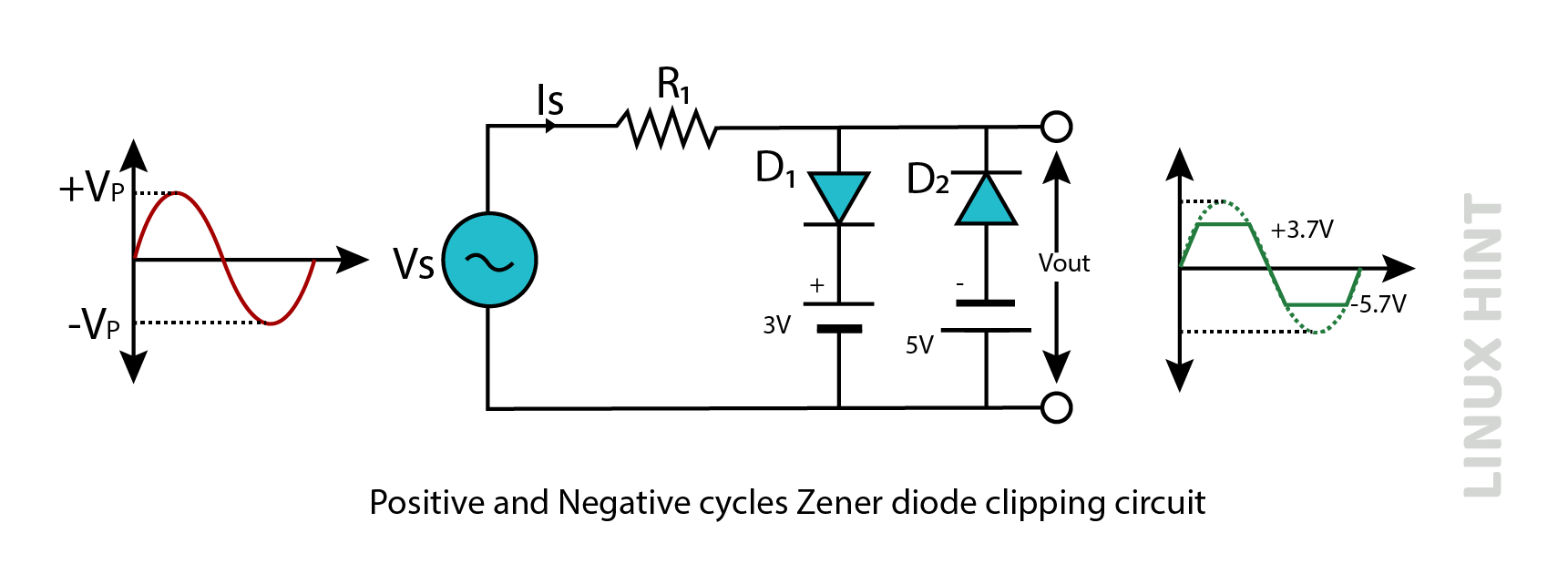
Cutoff occurs at +3.7V and -5.7V for positive and negative circuits, respectively, when using +0.7V and -0.7V thresholds.
Zener Diode Clipper
A Zener diode clipper is a common component used to limit signal amplitude in electronic systems.
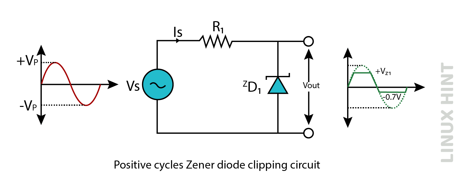
A clipping circuit requires a bias voltage input, increasing both the complexity as well as cost of the circuit. A Zener diode works just like a diode in a forward bias arrangement. When reversed biased, the Zener diode starts conducting electricity after the voltage exceeds the Zener voltage value. Both cycles are trimmed off using a Zener diode. In negative cycles, the Zener diode operates below this forward voltage drop, and in positive cycles, above the Zener voltage (VZ).
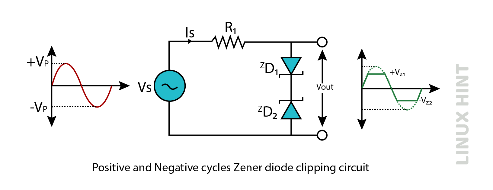
Zener Diode Full Wave Clipper
The picture below shows a full-wave clipper based with two Zener diodes. In this circuit, both circuits are limited by Zener diodes with Zener voltages (VZ). Simply put, ZD1 is used for limiting positive half cycles to VZ1 and VZ2, while ZD2 is used for limiting negative half cycles to VZ1 and VZ2.
Conclusion
The function of the diode clipper circuit is to limit or equalize the voltage to a certain limit. Trimming or modifying the level of the output waveform is dependent on both characteristics of the input signal and the characteristics of the circuit.