Transformer Construction and Transformer Core Design
Transformer design and ratings are all based on the individual design of its components. The design of windings and their turn ratios, selection of core type, and lamination are key factors in single-phase transformers. Three-phase transformer design adds a lot more factors including short circuit ratings, winding connections, and weight of transformer windings.
We will be discussing the design configurations in the case of single-phase transformers in detail below.
Transformer Construction
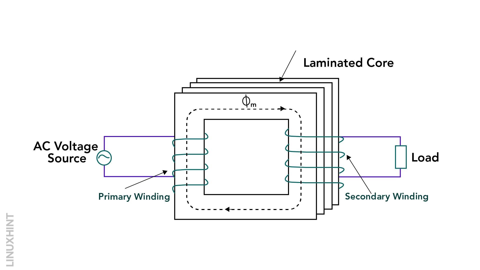
A transformer comprises two windings and an iron core body. The two windings are wound separately on the two limbs of an iron core, and there is no electrical connection between them. The magnetic field between the two windings is responsible for the electromagnetic induction and operation of the transformer.
Transformer Core Design
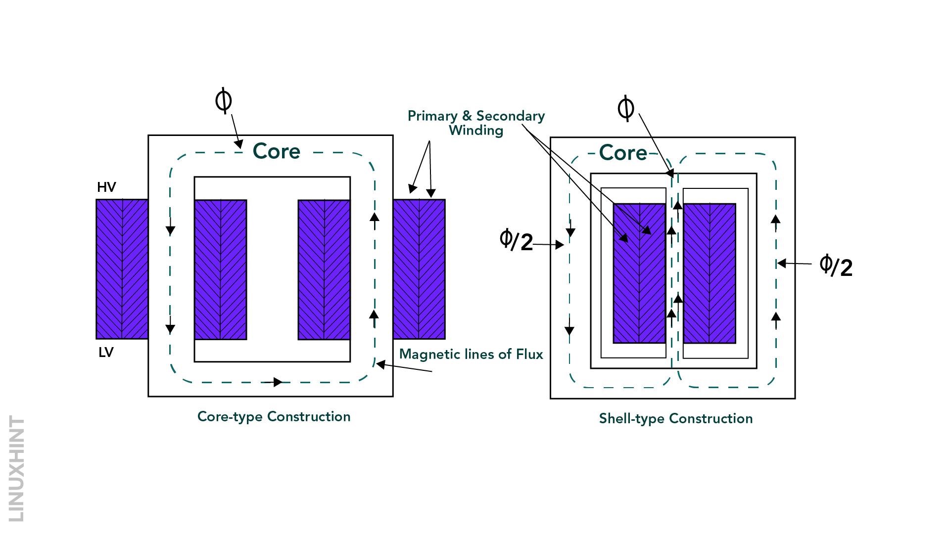
Based on the design, the transformer can be classified into two types; shell and core type design. In the core type, the transformer core is wound outside and around the core while in the shell type, the core is wound completely inside resembling a shell.
Winding and Core Lamination
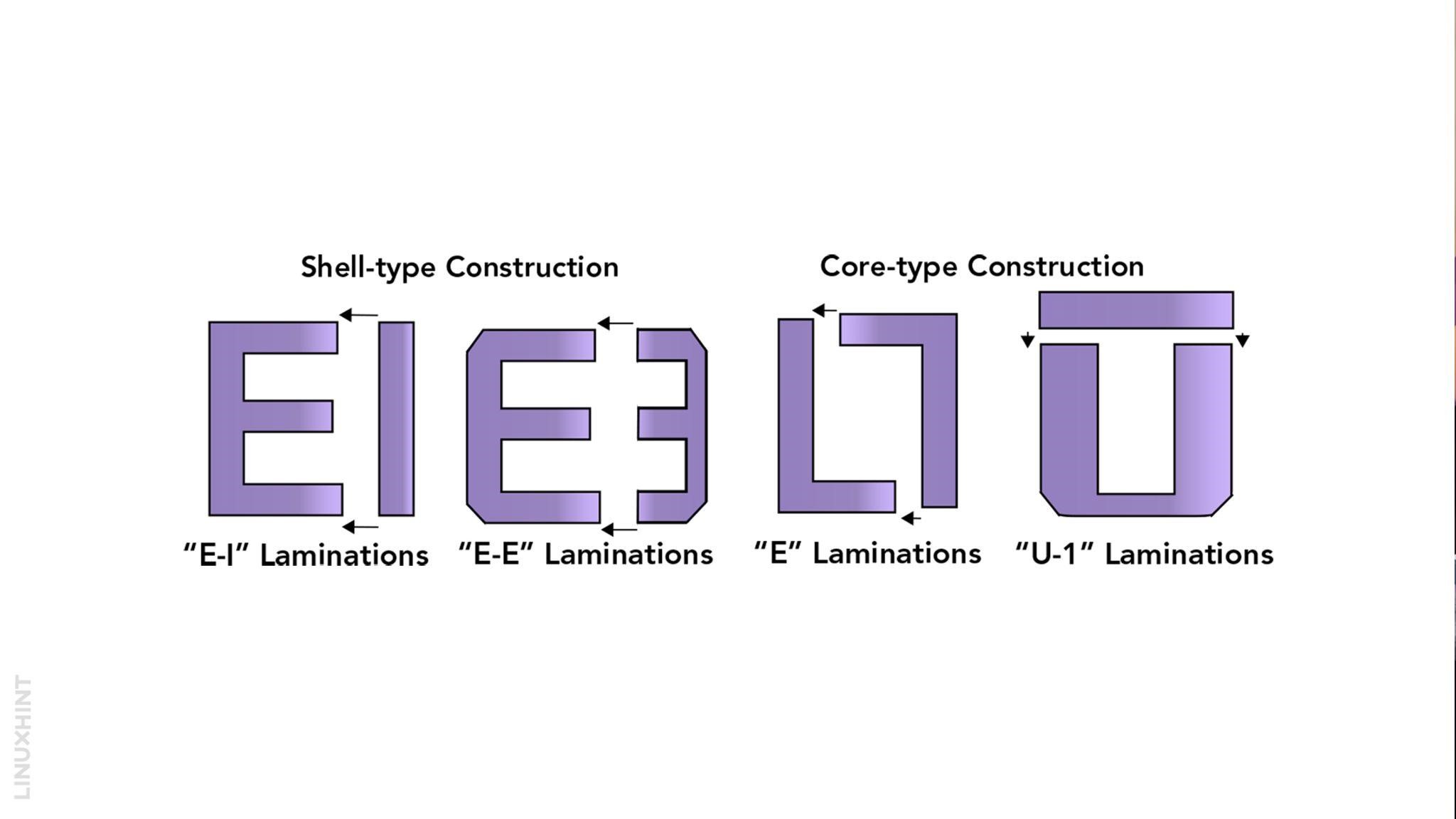
Laminating the iron core of a small transformer requires precision. The lamination is punched out from the core in the form of letters L, U, I & E from larger sheets to mount the windings. The punched-out lamination is arranged in such a manner that when combined, they make up the shape of core and shell-type transformer cores.
Transformer Windings Types
Primary and secondary windings are differentiated on the connection of voltage supply. The winding connected with supply voltage is called primary, while the other winding receiving the electromagnetic inductions is called secondary winding.
Depending upon construction, windings can be classified into below types:
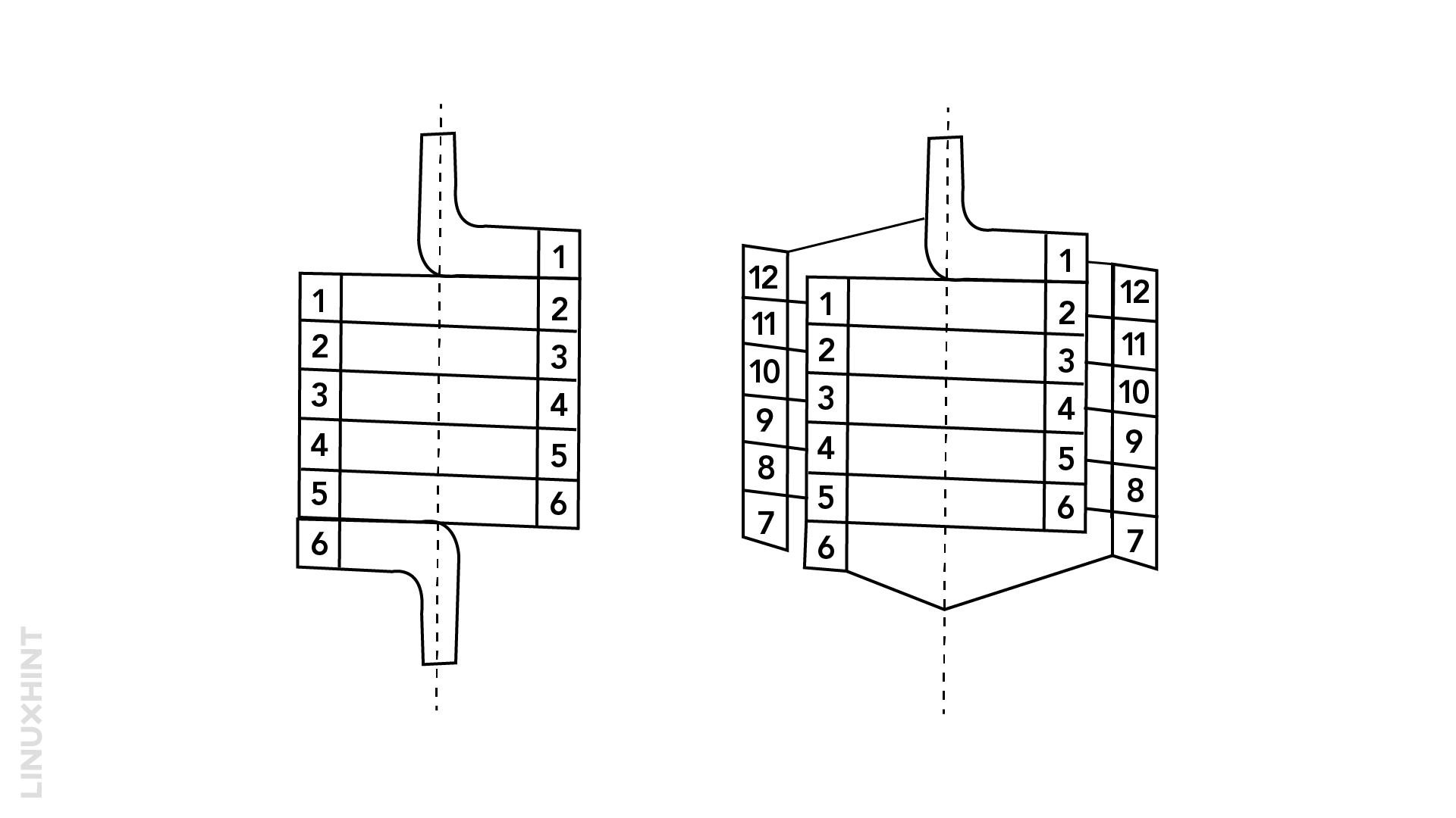
1: Helical Windings
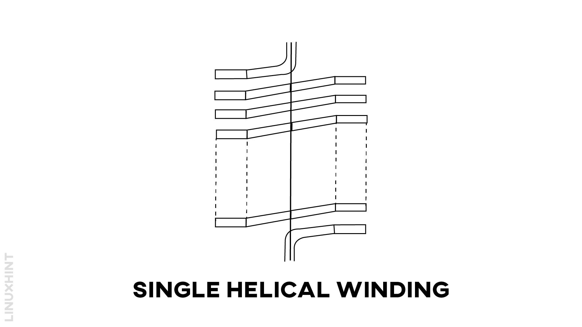
Helical windings follow an axial pattern along a centerline. These windings look like rectangular blocks, and usually, insulating discs or spacers are placed between their turns to reduce induced currents.
2: Cylindrical Windings
Cylindrical windings comprise cylindrical conductors. The cylindrical conductors can sometimes take the shape of a rectangle and are wound on a flat surface, as shown in the figure.
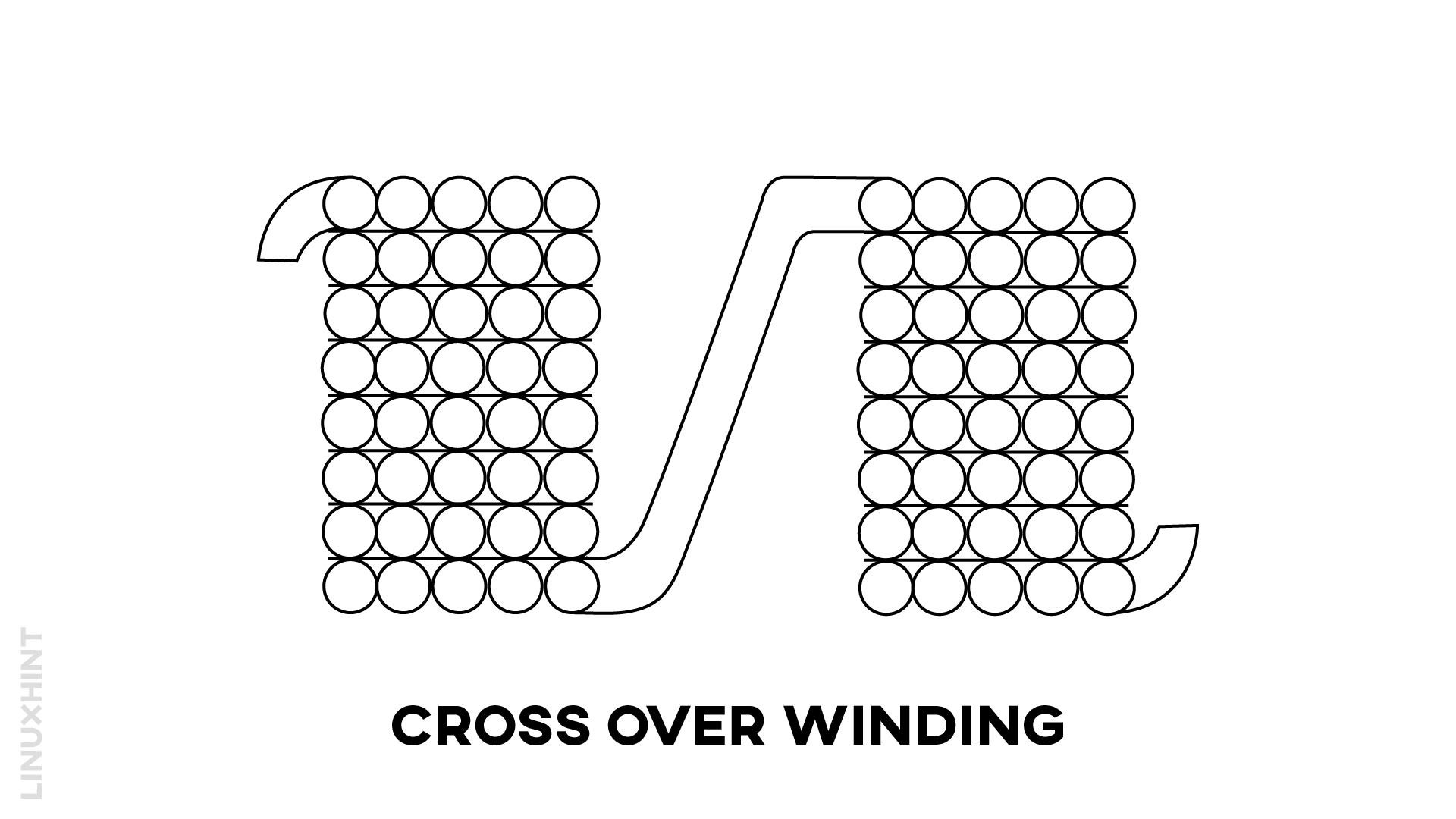
3: Crossover windings
These windings take the shape of round coils along with separation up to 1 mm between them. The crossover windings are utilized in high voltage requirements.
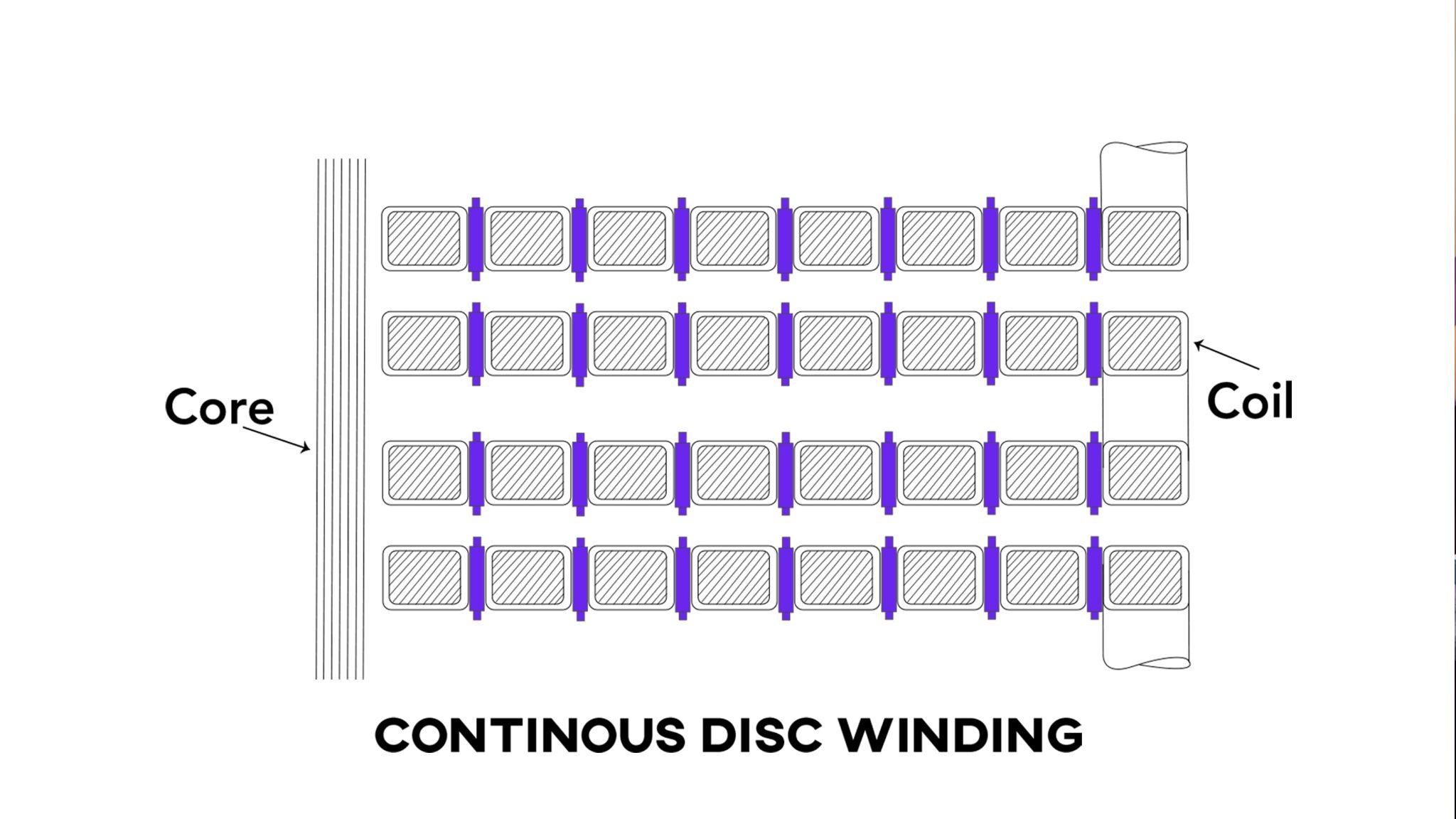
4: Disc Windings
Disc windings take the shape of a large number of discs placed against each other in a row. The conductor used to form the disc can range from single to multiplier as per the current requirements.
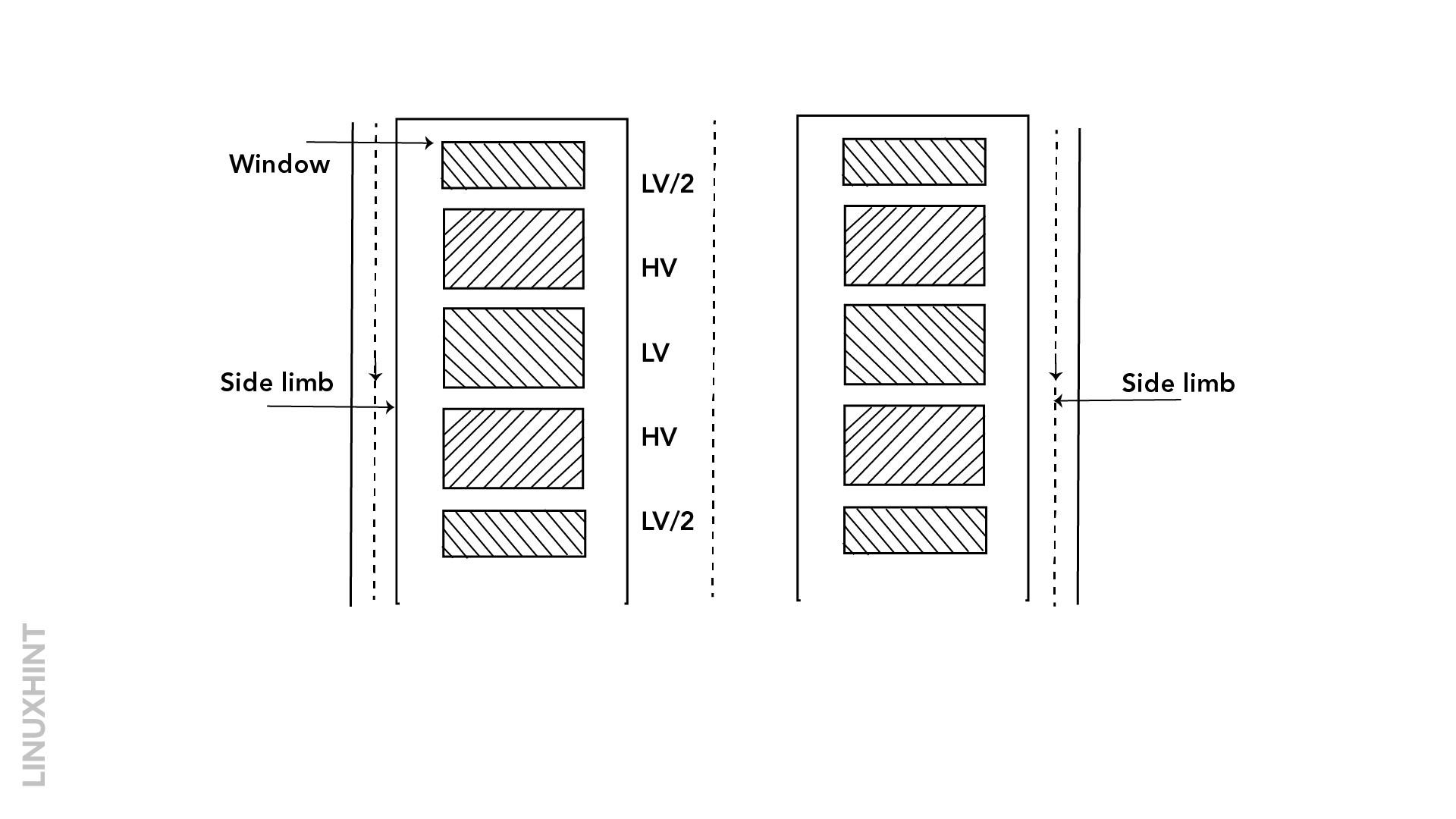
5: Sandwich-type Windings
The HV winding and LV winding is divided into many smaller sections. In these windings, an HV winding section is sandwiched between two LV winding sections, as shown in the below figure.
Dot Conventions on Transformer Windings
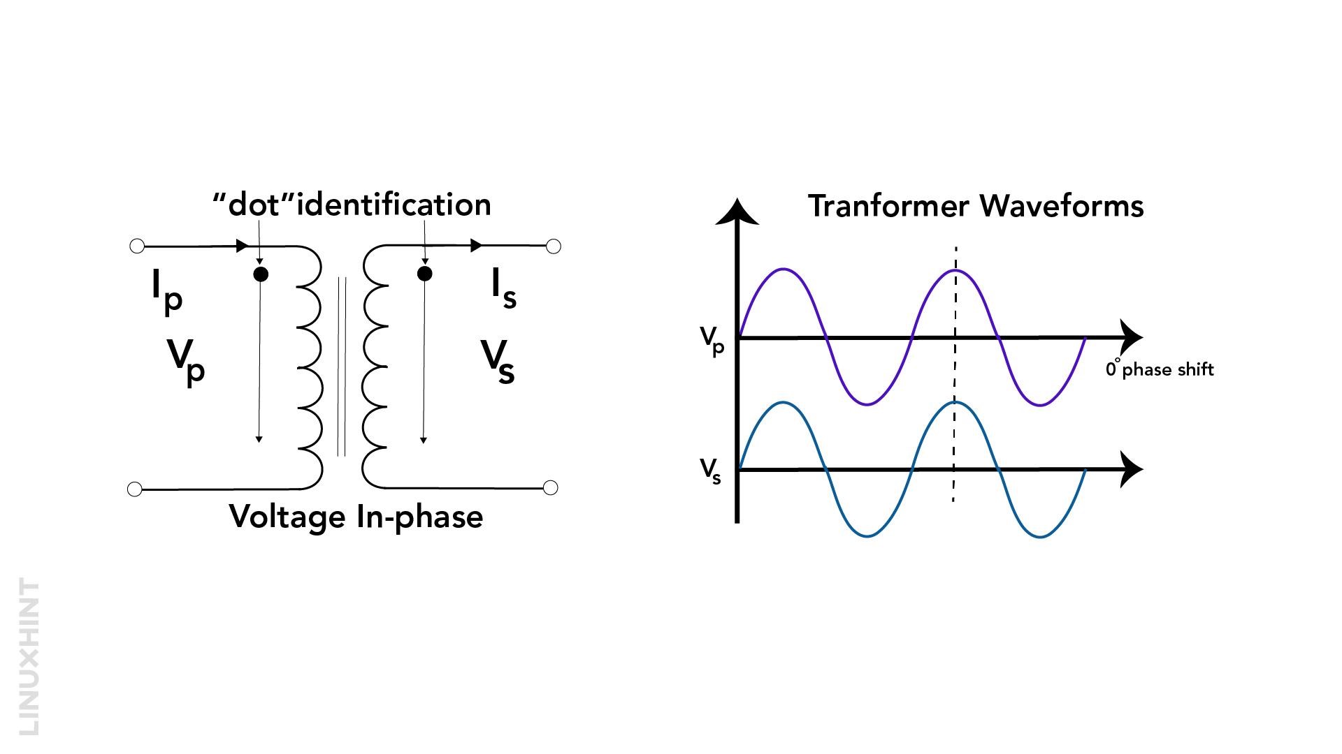
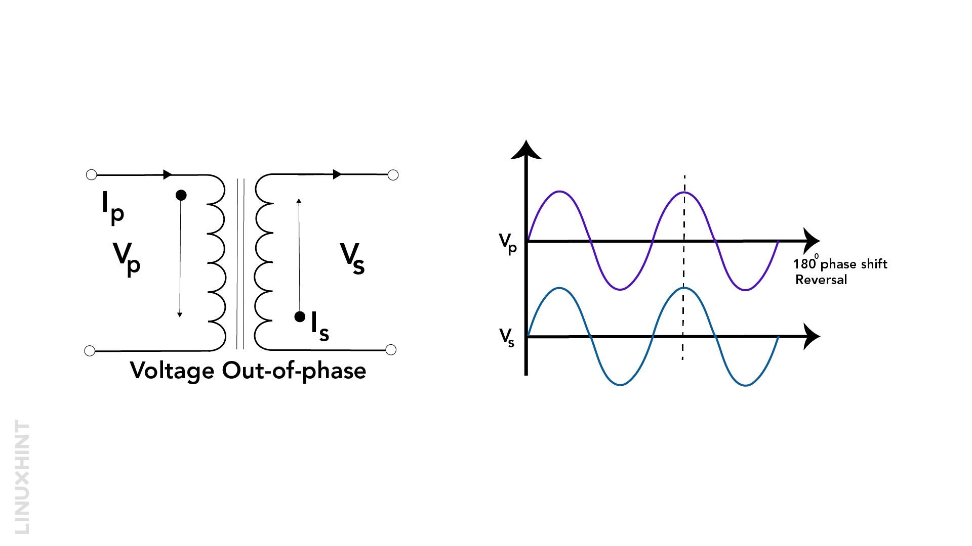
The dot conventions represent the phase-in & phase-out between the two windings. By phase-in, it means that there is no phase shift between primary and secondary winding voltages while phase-out means primary and secondary winding voltages have phase shifts in between them.
Phase-In Dot Convention
Phase-in means there is no phase difference between the two windings, and the positive peak of AC voltage at any instant on primary winding would mean the positive peak AC RMS voltage on secondary winding as well. The Phase-in is presented with two dots placed on the same side of the two windings, as shown below.
Phase-Out Dot Convention
Phase-out means a phase shift of 180 degrees. In other words, if there is a positive peak of AC voltage on the primary winding, there is a negative peak of AC voltage on the secondary winding. The Phase-out is presented with two dots placed at the opposite sides of two windings as shown below:
Conclusion
The transformer’s basic design comprises two windings and an iron core body. However, the variations in windings and core designs depend mainly on the output current and voltage requirements. The other factors important in selecting the right transformer design include short circuit ratings, temperature variations, and impedance.

