Oscillator circuits produce periodic signals at the output. They can convert any DC signal into AC signal with different frequencies depending upon its composition. We will discuss the Wien bridge oscillator, its working principle along with modified versions and examples in this article.
The Wien Bridge Oscillator
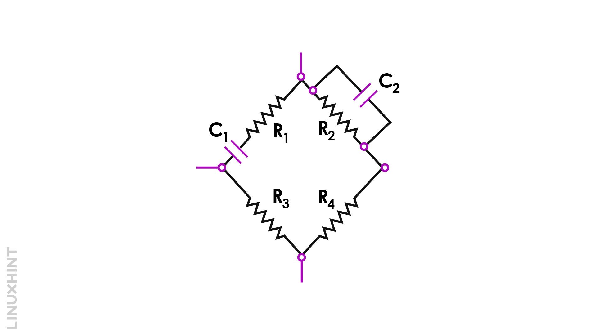
The Wein bridge oscillator is the frequency-oriented form of Wheatstone bridge. In its bridge formation, two arms contain only resistances, while the other two contain resistance and capacitor combinations. One of the arms of the bridge oscillator consists of a series RC circuit with another parallel RC circuit as shown below:

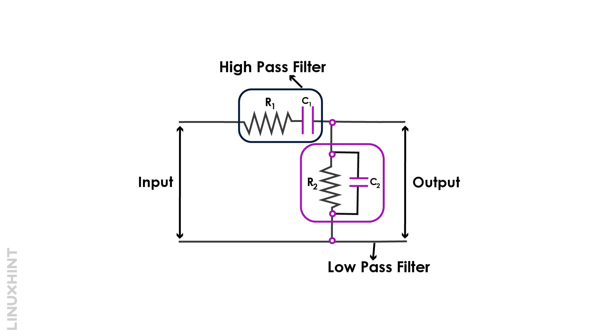
The capacitor-resistor combinations of two arms look like high pass and low pass filters as identified in below figure:
Working Principle
When lower frequencies are applied, the series capacitors offer very high reactance since the reactance of a capacitor is inversely proportional to frequency as given by:
Due to very high reactance, the capacitor behaves as an open circuit and therefore output remains zero.
When higher frequencies are applied, both of the capacitors C1 & C2 offer low reactance and act like a short circuit. In this situation, the input signal follows the short-circuited path from C1 & C2 to return to the supply. The output voltage remains zero in this case as well.
However, we can select a mid-frequency range in between very high frequency and very low frequency, so that both open-circuit and short-circuit conditions can be avoided. The mid-level frequency at which output voltage appears to be maximum is known as the resonant frequency.
Graphical Representation
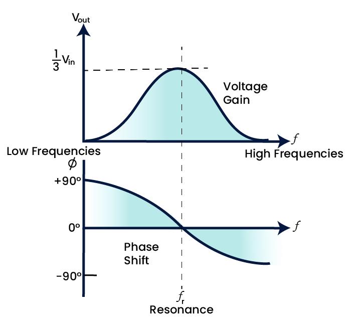
At the resonance frequency, the magnitude of output equals almost one-third of the input voltage. The graph, when plotted between output gain and phase shift, provides an illustration of phase advance, phase delay, and resonance point as shown below:
At low frequencies, the phase angle shows +90 degrees, indicating phase advance between input and output signals while at high frequencies, the phase angle becomes -90 degrees indicating there will be a phase delay between input and output signals. The mid-frequency point, fr indicates resonant frequencies where two signals are in phase with each other.
At low frequencies, the phase angle shows +90 degrees, indicating phase advance between input and output signals while at high frequencies, the phase angle becomes -90 degrees indicating there will be a phase delay between input and output signals. The mid-frequency point, fr indicates resonant frequencies where two signals are in phase with each other.
Oscillator Frequency Expression
The resonant frequency is calculated below:
For resonant frequency; R1=R2=R & C1=C2=C:
Wein Bridge Oscillator with Op-Amp
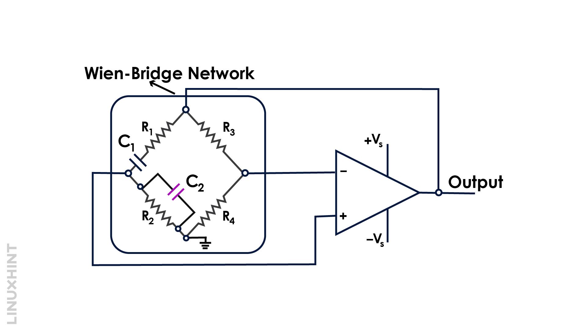
Wein bridge oscillators can also integrate op-amps in their circuit. The op-amps terminals are connected to the two points of the Wein bridge oscillator as shown below:
The only limitation of this configuration is the limitation of higher frequencies. The op-amps-based Wein bridge oscillators should be operated below 1 MHz. This is due to the fact that Wein bridges are low-frequency oscillators between 20Hz to 20kHz.
Example
Consider a resistor of 20kΩ and a variable capacitor of 10nf to 2000nf in the Wein bridge oscillator circuit. Evaluate maximum and minimum values of frequencies of oscillation.
The frequency of oscillations is given by:
For the lowest frequency, fmin;
For the highest frequency, fmax:
Conclusion
The Wein bridge oscillator is a combination of high-pass and low-pass filter networks. It operates at the resonant frequency where the output voltage appears to be maximum. Above and below this frequency, zero output is maintained.


