Op-amp Integrator, Operational Amplifier
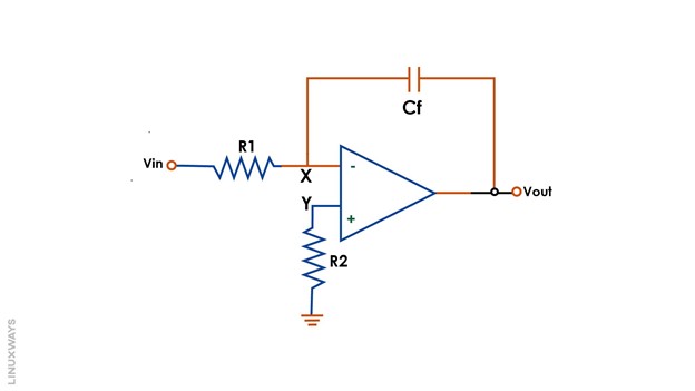
An op-amp integrator is a type of inverting op-amp amplifier whose feedback resistor has been changed with a capacitor. This conversion turns the op-amp inverter into an op-amp integrator circuit as shown below:
The output of such an op-amp configuration is an integration of the input. The feedback path of an op-amp integrator takes the form of a resistor-capacitor (RC) based circuit.
Working Principle of Op-amp Integrator Circuit
The output of an op-amp integrator is not only based on the input signal and also the time for which the signal has been applied. The working of the op-amp integrator is described below:
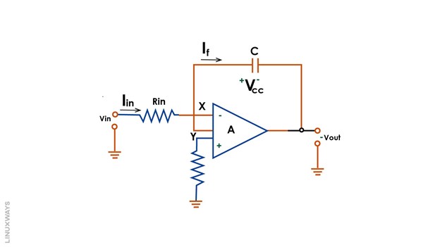
As soon as the input voltage is applied, the capacitor behaves as a short circuit and conducts current across its terminals. Since the capacitor offers very low impedance, the current flows from the input terminal via the capacitor to the output terminal. There is no input at the inverting terminal of the op-amp in this case due to the maximum flow of current through the capacitor path and the presence of zero earth potential at node X in the above circuit.
The capacitor continues to build charge across its terminals with time, and its impedance continues to rise as well. The gain ratio for the capacitor circuit denoted by Xc/Rin also rises with an increase in impedance till the capacitor reaches a fully charged condition.
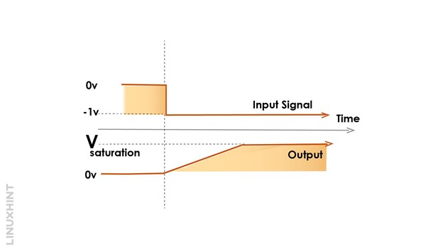
In fully charged conditions, capacitor impedance rises to the maximum value, and it now behaves as an open circuit. The voltage drops Vc across its terminals due to high gain, and the op-amp reaches its saturation state as shown in the below diagram:
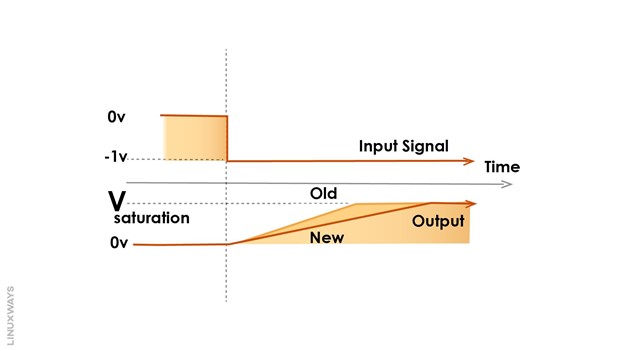
The product of the resistor and capacitor value is known as the time constant. The time constant (RC) defines the time required for a capacitor to reach its fully charged condition. It is changeable, as both the values of resistance R and capacitor C can be changed to vary the period of charging the capacitor. The figure below shows the adjustments of values of resistance R and capacitor C resulting in the charging of the capacitor in a linear pattern:
Derivation of Output Voltage Expression
We can prove mathematically that the output voltage is the negative integral of the input voltage. The stepwise derivation of the output voltage is described hereafter.
The voltage across the capacitor is expressed as:
Applying KVL for VC:
For the rate of change of time, multiplying the above equation with d/dt:
Also, the input current can be expressed as:
The capacitor current in the feedback loop is calculated as:
Substituting:
Also, the current flows through a capacitor in the circuit and the op-amp has an infinite impedance value:
Rearranging the equation:
Applying integrator operator:
Ramp Generator Application of Op-Amp Integrator
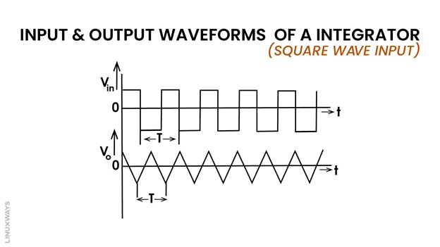
The op-amp integrator converts to a ramp output generator when the input voltage signal is a uniform time-varying signal such as a square wave. The capacitor will charge during the positive half and discharge during the negative half resulting in sawtooth output as shown below. Such an arrangement is referred to as a ramp generator. As seen below, ramps output resembles triangular shape outputs.
During the positive half of the square wave, the capacitor continues to build charge and the current flows through the feedback path of the capacitor, resulting in zero input current at the op-amp terminal. The output voltage of the op-amp shall appear at the capacitor during the charging situation.
During the negative half of the square wave, the charged capacitor now produces positive triangular outputs.
AC Op-Amp Integrator with Controllable DC Gain
In an AC op-amp integrator, the input is a frequency-varying sinusoidal wave. The capacitor in the feedback path at very low or zero frequency behaves like an open circuit, resulting in the removal of the feedback path. Without feedback, the op-amp gain becomes uncontrollable.
In the case of standard frequency, the op-amp works as a normal integrator. However, in the case of high frequency, the capacitor behaves like a short circuit, and current flows through the capacitor.
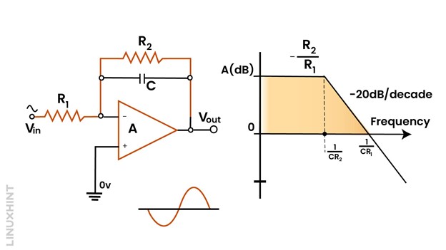
To limit gain in an open circuit case, a feedback path shall be present in the open circuit condition. This is achieved by adding a high-value resistor R2 in parallel to the capacitor to limit the voltage gain as shown below:
Now at low frequencies, the capacitor behaves as an open circuit, but DC voltage gain is now controllable and given by R2/R1. Also, in the case of an AC integrator, the output will be 90 degrees out of phase with input as shown above.
The above working principle follows the low pass filter operation. It permits low frequencies but blocks higher ones.
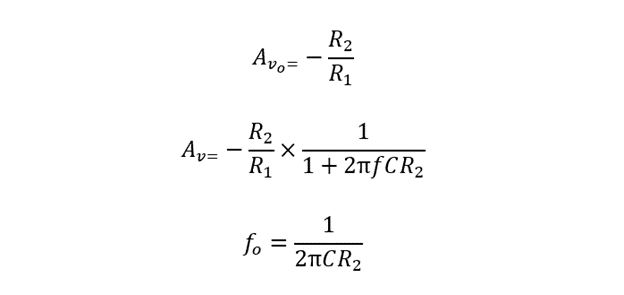
The below expressions of DC voltage gain AVo, AC voltage gain AC along with corner frequency fo shall be applicable in case of AC op-amp integrator:
Conclusion
The integrator op-amp circuit relies on two parameters; the amplitude of input voltage along with the time for which it is applied at the input terminal. It is an inverting op-amp whose feedback has been changed from a feedback resistor to a feedback capacitor.

