Differential Amplifier – Voltage Subtractor
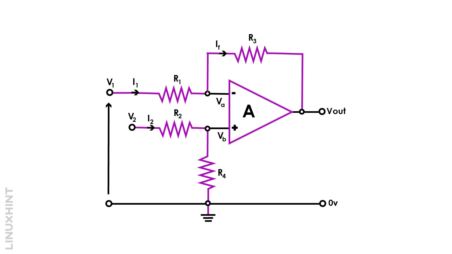
When two distinct voltage inputs are applied to the operational amplifier’s two terminals, it functions as a differential amplifier. The amplifier in such a configuration subtracts the voltages at inputs and then amplifies its voltage difference. In the differential amplifier case, two different voltages are applied as shown below:

The major reason for including the feedback path is to achieve a controllable voltage gain. Without the feedback path, the open loop gain may reach a very high indeterminate value and the operation of the op-amp would not be as per the design requirements. The addition of a feedback path with a feedback resistor R3 along with voltage dividers R2 & R4 keeps the voltage gain within the controllable limits.
In the above figure, V+ denotes non-inverting terminal voltage while V– is inverting terminal voltage. On the non-inverting terminal, resistances R2 and R4 act as voltage divider circuits with V2 input voltage and V+ as the output voltage. The Vout =V+ for the above voltage divider configuration at the non-inverting terminal is given by:
In the above figure, the current entering node and leaving node shall be the same; so:
Applying KCL:
The op-amp tends to maintain input voltages at the same value when applied to its two terminals:
Using the expression of V+from the first equation above in KCL:
If resistor values are the same; R2=R1:
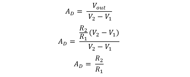
The differential op-amp gain now be calculated as the ratio of Vout to different input voltages V1 – V2:
Common Mode Voltage Gain
Considering the two input voltages are the same, then in this case it looks obvious that the voltage subtractor shall provide a zero output. However, in practical cases, there still exists a minor voltage output in ranges of microvolts when common input signals are applied.
The common mode op-amp gain is given by:
Common Mode Rejection Ratio
Common mode input voltages are not desired in differential amplifiers. Op-amps tend to reject common mode signals, and this ability to oppose such signals is defined in terms of CMRR.
The ratio of differential mode gain (Ad) to common mode gain (Ac) is defined as the common mode rejection ratio, as given below:
CMMR can also be expressed in decibels (dB):
Output Voltage in Common Mode Configuration
Similarly, in common code, the common voltage expression can also be derived as:
The output voltage of the differential op-amp shall be modified as:
Example
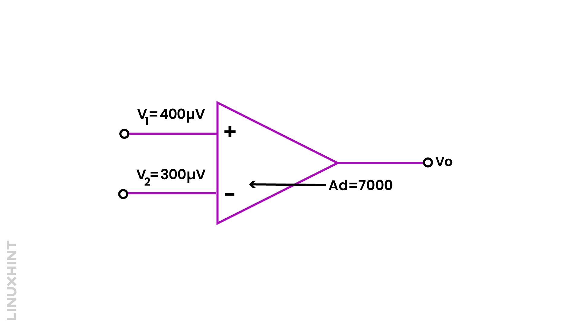
Calculate the output voltage of differential op-amp with input voltages V1=400µV & V2=300µV, Ad=7000, CMRR=500 as shown in the below configuration.
As we know:
In common mode, VOUT is given by:
For VDM and VCM, we can calculate as:
Substituting in VOUT:
Conclusion
The differential operational amplifier subtracts input voltages when two different voltages are applied at its two terminals. The output is an amplification of the difference in input voltages. In this tutorial, we discussed differential amplifiers in detail.


