What are Series Circuits?
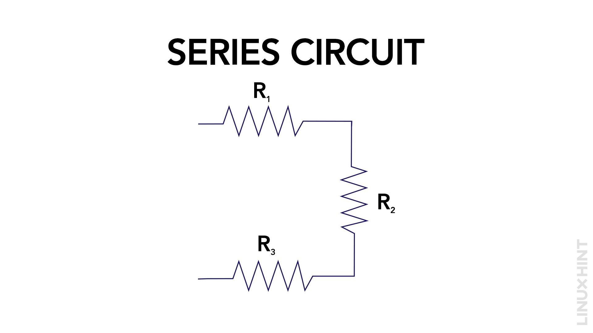
In a series circuit, the components are interconnected consecutively, establishing a singular pathway for the flow of electric current. Consequently, the current passes through each component are the same, whereas the voltage across each is different.

Example of a Series Circuit
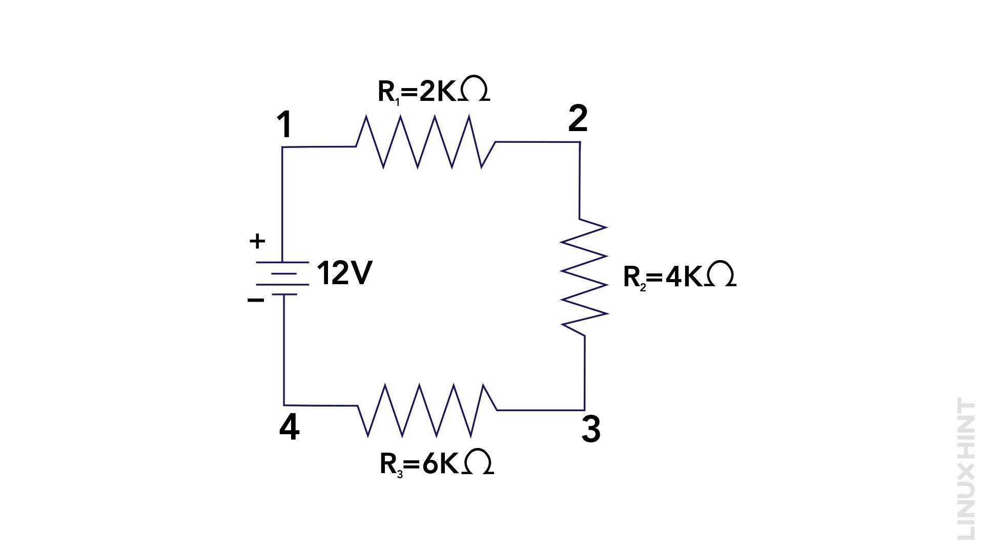
For illustration, examine a basic series circuit comprising three resistors connected sequentially. If we denote the resistance values as R1, R2, and R3, the total resistance (RT) would be the sum of these individual resistances:
If the value of R1= 2 K ohms, R2 = 4 K ohms, and R3 = 6 K ohms then, in that case, the equivalent resistance can be calculated using the above-given formula as:
In a series circuit, the current passing through every resistor remains constant, regardless of their individual resistance values. However, the voltage across each resistor may differ based on its specific resistance value.
What are Parallel Circuits?
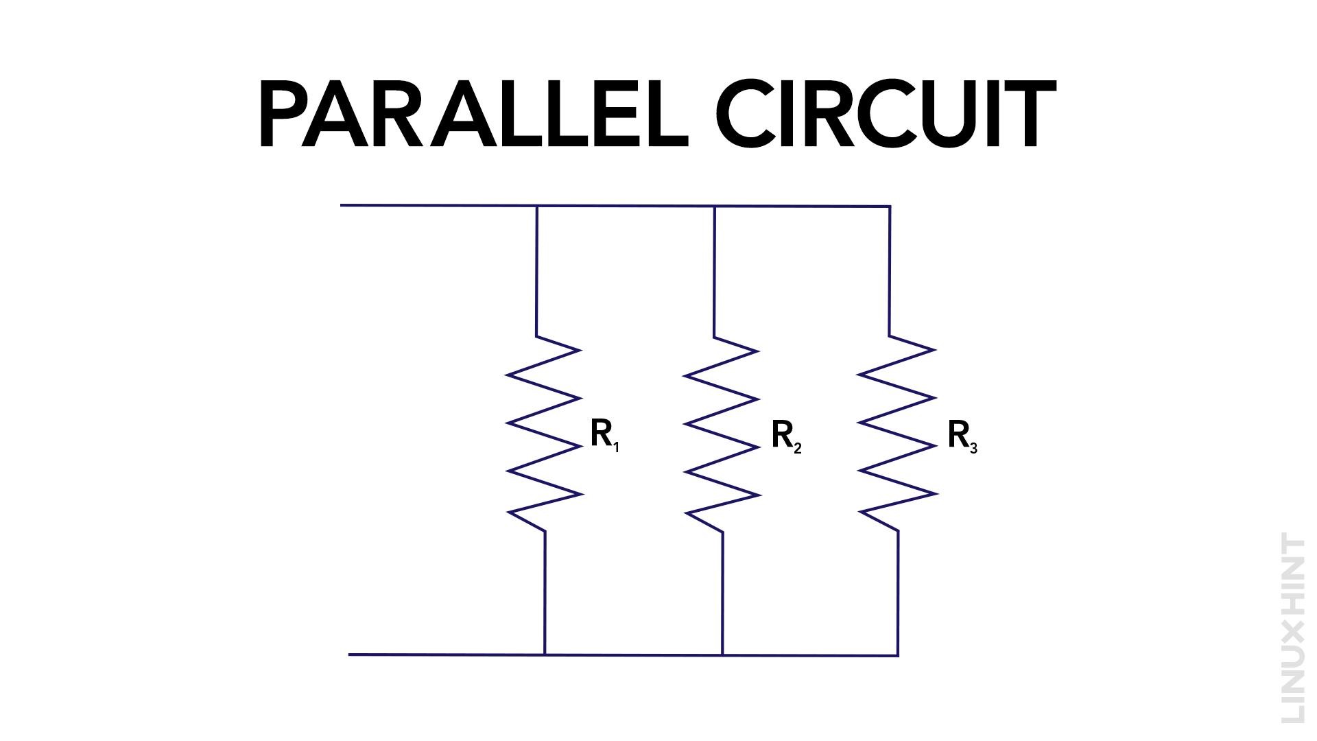
In a parallel circuit, the components are connected in such a way that there are multiple pathways for the flow of electric current. In a parallel circuit, the current divides and flows independently through each component, as a result, the voltage across each component remains constant. Nevertheless, the total current in the circuit equals the combined sum of the individual currents flowing through each branch.
Example of a Parallel Circuit
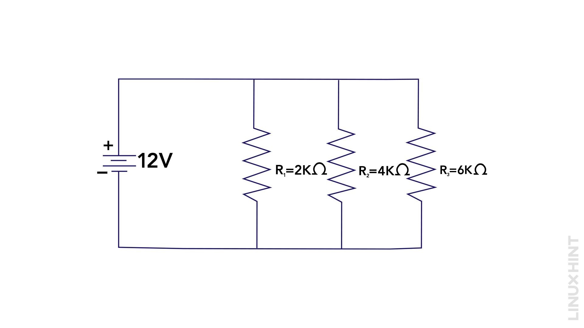
Here is a parallel circuit with three resistors connected in parallel, denoting the resistance values as R1, R2, and R3, the total resistance (RT) can be calculated using the following formula:
If the value of R1= 2K ohms, R2 = 4K ohms, and R3 = 6 K ohms then, in that case, the equivalent resistance can be calculated using the above-given formula as:
In a parallel circuit, the voltage across each resistor remains consistent, irrespective of their individual resistance values. However, the current passing through each resistor may fluctuate depending on its specific resistance value.
Differences between Series and Parallel Circuits
To better understand the disparities between series and parallel circuits, let’s summarize their key differences in the following table:
| Aspects | Series Circuits | Parallel Circuits |
|---|---|---|
| Current Flow | Same current flows through every component | Current splits and flows independently through branches |
| Total Resistance | Sum of individual resistances | Reciprocal of sum of reciprocal of individual resistances |
| Voltage across components | Voltage spit across components | Voltage remains same across components |
| Component failure | Failure of one component disrupts the entire circuit | Failure of one circuit doesn’t disrupt the entire circuit |
Conclusion
In series circuits, the components are interconnected sequentially, allowing the same current to flow through each element. On the other hand, in parallel circuits, the components are linked in distinct branches, resulting in the division of current and independent flow through each branch.


