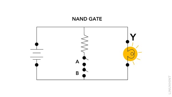
NAND Gate
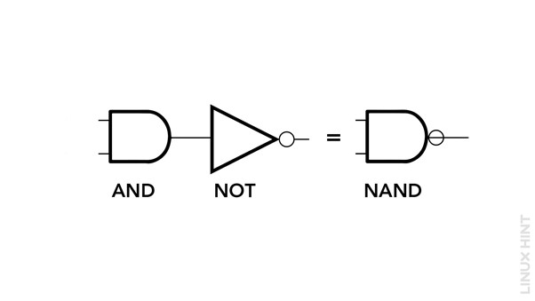
The NAND gate is a universal gate, meaning that it can be used to implement any logical function. It is an inverted AND gate, where the output is the complement of the AND operation’s result. The gate can have multiple inputs and a single output, and will give a low on output when all the inputs are high:
| A | B | Output |
|---|---|---|
| 0 | 0 | 1 |
| 0 | 1 | 1 |
| 1 | 0 | 1 |
| 1 | 1 | 0 |
As seen in the truth table, the output of the NAND gate is only 0 when all inputs are 1 and in all other cases, the output is 1. The logic equation for a 2-input NAND gate can be represented as follows:
In this equation, the AND operation is performed between the inputs (Input A and Input B), and the result is negated using the NOT (inversion) operation.
Example
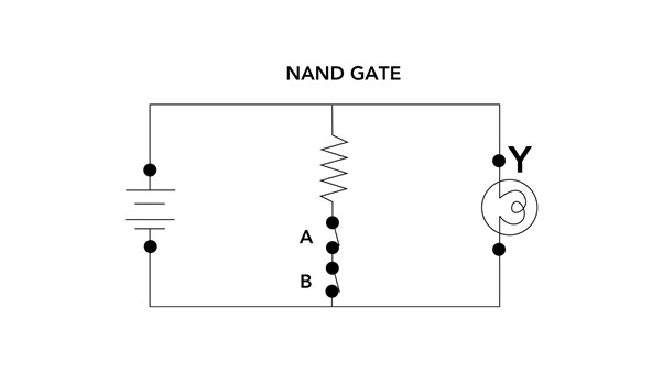
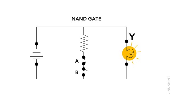
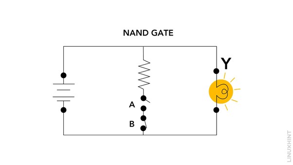
Consider a situation where a NAND gate is used to control the power supply to a light bulb in a room. In this case, the two inputs represent the states of two switches.
When both the inputs are high for the NAND gate then:
When switch A is closed and switch B is open as one input for the gate is high and the other is low then:
When switch A is open and switch B is closed as one input for the gate is high and the other is low then:
When both the inputs are Low that is both the switches are open for the NAND gate then:
Conclusion
The NAND gate is a versatile component in digital logic circuits, serving as a building block for designing complex logical operations. Its truth table, equations, and practical examples have been discussed in this tutorial.


