What is a Transformer?
A transformer is an electromagnetic device that facilitates the wireless transmission of electrical energy between multiple wire coils, commonly known as windings. It functions according to electromagnetic induction theory. A transformer’s primary winding, secondary winding, and iron or other ferromagnetic material–based core are its essential parts.
Working of a Transformer
A device known as a transformer uses electromagnetic induction to transmit electrical energy across multiple circuits. It is made up of two or more winding coils of insulated wire wound around a single magnetic core. The primary winding and secondary winding are a transformer’s two main parts.
Faraday’s law of electromagnetic induction is the essential idea that drives a transformer’s operation. According to this law, when the magnetic field that connects two conductors changes, an electromotive force (EMF) is induced in the conductor. This induction of EMF in a transformer happens as a result of the shifting magnetic field created by alternating current (AC) passing through the primary winding.
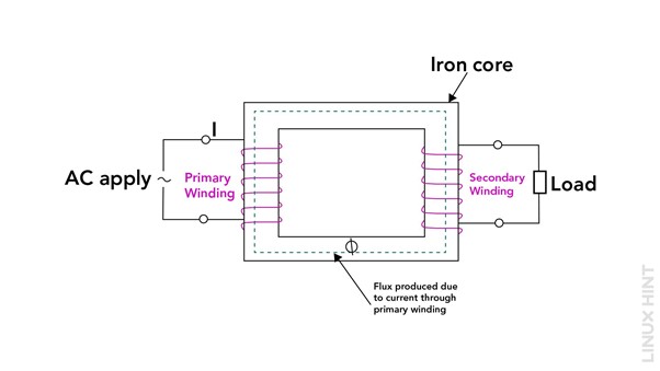
An alternating current is created by connecting the primary winding to an AC power source. The primary winding is surrounded by a magnetic field as the AC flows through it. Following the changes in the AC waveform, this magnetic field continuously grows and contracts.
The primary winding’s magnetic field interacts with the secondary winding and creates an EMF there. The strength of the induced EMF is determined by the turning ratio of the transformer, which is the total number of turns in the secondary winding divided by the number of turns in the primary winding.
Alternating current flows through the secondary winding as a result of the produced EMF. This current can be of higher or lower voltage, depending on the turn ratio and the design of the transformer. The load or gadget that needs electricity is linked to the secondary winding.
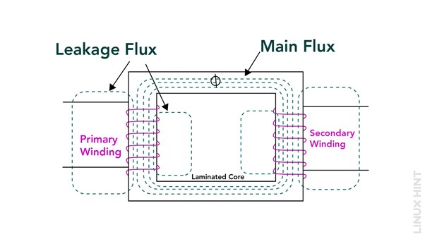
The primary winding’s magnetic flux travels via a low-reluctance path through the magnetic core, which is often comprised of laminated iron or steel Between the primary and secondary windings, it aids in the effective passage of energy.
EMF of a Transformer
According to Faraday’s law, when a varying current flows through the primary winding, it induces a varying magnetic field in the core. This varying magnetic field then links with the secondary winding, resulting in the generation of a voltage across the secondary winding and the EMF can be calculated using:
Where:
EMF is the electromotive force (voltage) induced in the secondary winding.
N is the secondary winding’s turn count.
The magnetic flux linkage’s rate of change with the secondary winding is represented by the ratio dΦ/dt.
Turns Ratio of a Transformer
The turns ratio is defined as the sum of the turns in the primary winding and the turns in the secondary winding.
A transformer’s turns ratio (N) is calculated by multiplying the total number of turns in the primary winding (Np) by the number of turns in the secondary winding (Ns).
Power of a Transformer
In an ideal transformer (with no losses), the power input on the primary side is equal to the power output on the secondary side. This relationship can be expressed as VP × IP = VS × IS, where VP and IP represent the voltage and current on the primary side, while VS and IS represent the voltage and current on the secondary side:
Here the power P is in watts (W), the current in amps (A), and the voltage volts (V).
Efficiency of a Transformer
How effectively a transformer transfers electrical energy is shown by the proportion of the output power to input power, often known as the transformer’s efficiency. It is an important parameter for assessing the performance of a transformer. The formula to calculate the efficiency of a transformer is as follows:
Where:
Output Power is referring to the power that the transformer’s secondary winding delivers. It is typically measured in watts (W) or kilowatts (kW) and represents the power available to the load connected to the secondary side of the transformer.
Input Power is usually measured in the same units as the output power and represents the power drawn from the source connected to the primary side of the transformer.
Types of Losses in a Transformer
To transfer electrical energy among multiple circuits, transformers use electromagnetic induction. During the energy conversion process, various types of losses occur within a transformer. The main types of losses in a transformer are:
Copper Losses (I^2R Losses)
The resistance of the transformer’s windings causes copper losses, copper losses consist of two parts:
- Copper Loss in the Primary Winding: Current passing through the primary winding’s resistance is what causes this loss. It is inversely linked to the square of the resistance of the winding (R) and the current (I2) that flows through it.
- Copper Loss in the Secondary Winding: Similar to the primary winding, copper loss in the secondary winding is caused by the resistance of the winding and is proportional to the square of the current flowing through it. Copper losses generate heat within the windings and are proportional to the square of the current, leading to energy dissipation.
Core Losses (Iron Losses)
Core losses, often referred to as iron losses, occur in the magnetic core of the transformer as a result of the magnetization and the demagnetization of the core material, core losses come in two categories:
- Hysteresis Loss: With each alternating current (AC) cycle, the magnetic polarity of the core material reverses, resulting in hysteresis loss. This repeated magnetization and demagnetization of the core material results in energy loss due to molecular friction. Hysteresis loss is influenced by the alternating current’s frequency and the core material’s magnetic properties.
- Eddy Current Loss: The varying magnetic field causes circulating currents called eddy currents inside the core material. These currents circulate within the core and encounter resistance, resulting in energy dissipation in the form of heat. Eddy current losses can be decreased by using insulated or laminated core materials. Hysteresis and eddy current losses, which are proportional to the square of the voltage and the frequency of the alternating current, both contribute to core losses.
Types of Transformers
From power grid transmission to everyday electronics, transformers make it possible to harness electrical energy effectively. With their ability to step up or step-down voltage levels, transformers ensure a safe and reliable electricity supply for our daily lives. Based on their uses and design, transformers can be divided into various types:
Based on Voltage Levels
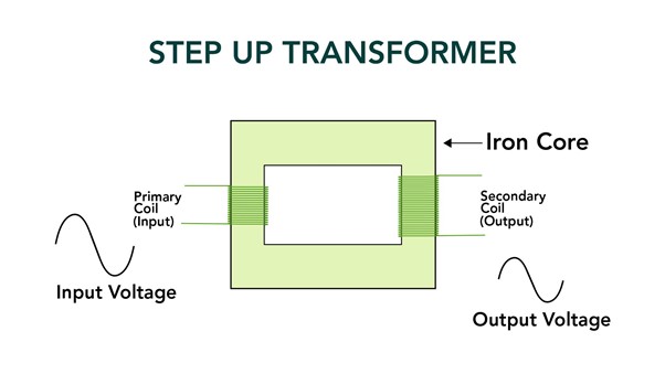
1. Step-Up Transformers: The voltage level is raised using step-up transformers from a lower value to a higher value. They are commonly used in power transmission systems to increase voltage levels for long-distance transmission, reducing losses and enabling efficient power transfer.
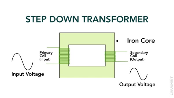
2. Step-Down Transformers: Transformers that use a step-down process drop the voltage level from a higher value to a lower value. They are widely used in power distribution networks to reduce high-voltage electricity to a safer and more usable voltage for residential, commercial, and industrial applications.
Based on Installed Location
1. Power Transformers: Power transformers are large-scale transformers typically installed at electrical substations. They are essential for both scaling down the voltage for distribution and transporting high-voltage power over great distances.
2. Distribution Transformers: Distribution transformers are smaller transformers found on utility poles or in underground vaults. They step down the voltage from the distribution network to the level suitable for individual consumers, such as households and small businesses.
Based on Per Phase
1. Single-Phase Transformers: Single-phase transformers are designed to handle single-phase AC power. They are frequently utilized in settings with minimal power demands, such as homes and small businesses.
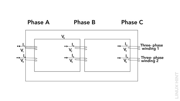
2. Three-Phase Transformers: Transformers for three-phase AC power are known as three-phase transformers. Since they offer improved efficiency and balanced power distribution, they are frequently utilized in industrial and commercial applications where there is a higher electricity demand.
Based on Core
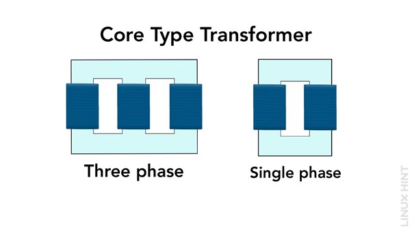
1. Core-Type Transformers: Core-type transformers have windings wound around a laminated magnetic core. A low-reluctance channel for the magnetic flux is provided by the core, resulting in effective energy transmission. Due to their dependability and simplicity of maintenance, core-type transformers are frequently preferred.
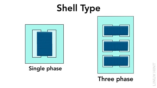
2. Shell-Type Transformers: Shell-type transformers have two separate coils (primary and secondary) wound around a central iron core, the core surrounds the windings like a shell. Shell-type transformers are used for low to medium-power applications and offer better cooling characteristics.
Based on Cooling System
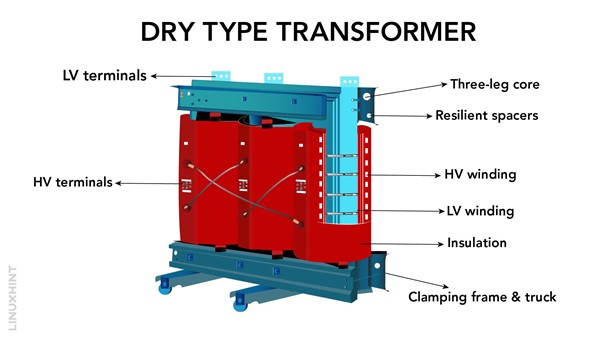
1. Dry-Type Transformers: Dry-type transformers use air or gas as the cooling medium. They are filled with non-flammable and non-toxic materials, making them safe for indoor installations. Dry-type transformers are commonly used in buildings, hospitals, and other areas where fire safety is crucial.
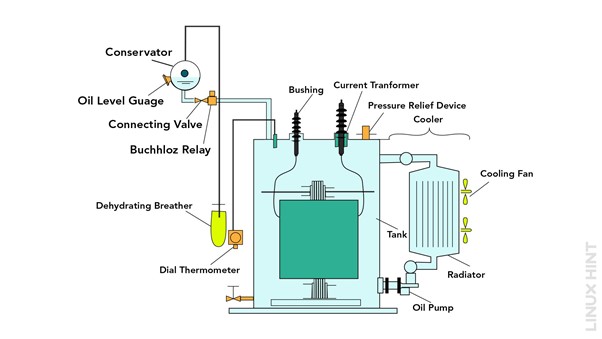
2. Oil-Immersed Transformers: Oil-immersed transformers are filled with insulating oil that not only provides cooling but also enhances insulation. The heat that is produced during operation is absorbed and released by the oil. These transformers are commonly used in outdoor installations and high-power applications, such as power generation and transmission.
Conclusion
Transformers are integral to the modern power infrastructure, enabling efficient transmission and distribution of electrical energy. By understanding the basic principles of transformers, such as Faraday’s law of electromagnetic induction, turns ratio, and conservation of energy, their usability can be enhanced.

