Arduino is an electronic development board that runs using a microcontroller. It processes instructions and generates the desired output. Communication plays a major role while processing Arduino code. To do so Arduino has multiple communication protocols such as USART, I2C, and SPI. To read more about communication protocols in detail click here. Today we will discuss how SPI (Serial Peripheral Interface) is used in Arduino.
Serial Peripheral Interface (SPI)
Serial Peripheral Interface (SPI) is a synchronous serial data protocol used by Arduino Microcontrollers for communication purposes with one or more peripheral devices quickly over short distances. It can also be used for communication between two microcontrollers.
SPI is a full duplex communication which means it can send and read data at same time. Among all three communication protocols (USART, SPI and I2C) in Arduino SPI is fastest. SPI has applications where high data rate is required such as displaying text on screens or writing data on SD card.
SPI works using four lines:
- SCK: Clock signal which synchronize data transfer between master and slave devices.
- MISO: (Master in Slave Out) or MISO is a data line for slave that can send data back to master.
- MOSI: (Master Out Slave In) or MOSI is a data line for master to send data to slave devices and peripherals.
- SS: (Slave Select) It is the line used by master to select a specific slave device. It informs slave device to which data is going to be sent or received.
Update: As per Arduino official documentation SPI in Arduino no longer supports these terminologies. Below table shows the new terminologies:
| Master/Slave (OLD) | Controller/Peripheral (NEW) |
| Master In Slave Out (MISO) | Controller In, Peripheral Out (CIPO) |
| Master Out Slave In (MOSI) | Controller Out Peripheral In (COPI) |
| Slave Select pin (SS) | Chip Select Pin (CS) |
SPI Pinout in Arduino Uno
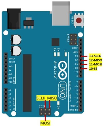
SPI protocol is supported by multiple Arduino boards here we discussed Arduino Uno support for SPI. Following are the pins used by Arduino Uno for serial peripheral communication.
| SPI Line | GPIO | ICSP Header Pin |
| SCK | 13 | 3 |
| MISO | 12 | 1 |
| MOSI | 11 | 4 |
| SS | 10 | – |
SPI in Master Slave Configuration
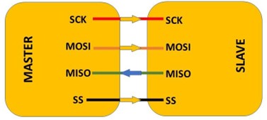
Connecting a master device to single slave is simple we just have to connect both of them with same pin. Once both master and slave device are connected like shown in image below. First, we have to set the SS (Slave Select Line) on master device to be LOW. It will remain LOW during the data transmission. LOW SS line prepare slave to send or receive data. Once the SS is LOW master, the device can send data using the MOSI line and can produce clock signals for synchronous communication using the SCLK pin.
SPI in Single Master Multiple Slave Configuration
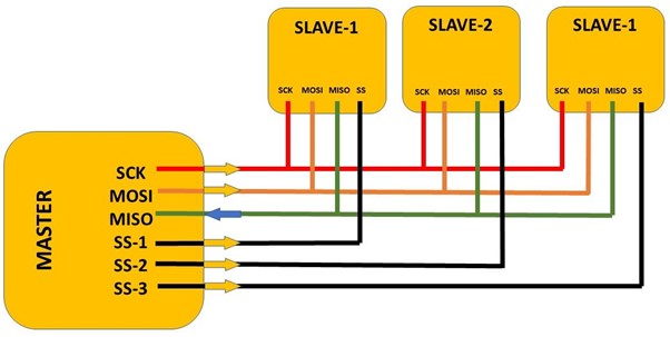
SPI also support multiple slave devices, a separate SS(Slave Select) line is used for every single slave. Unlike single slave here master need a separate SS line for each slave. Working of single and multiple slave devices configuration is somehow similar. Master device pull the SS line of particular slave to LOW which inform slave device that master is going to send or receive data from that slave.
Following image illustrate single master multiple slave device configuration.
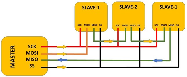
Daisy Chain Configuration is another way of connecting multiple slave devices. Where master do not need multiple SS line for each slave in fact a single SS line is connected to first slave device. Once the master device pulls the SS line to LOW it sends signals to all slave device to be ready for communication at MOSI pin. Then master device send data to MOSI pin of the first slave device.
At the same time the master sends a clock signal at the SCK pin. Data is sent from one slave to other and SS pin is set as LOW during this duration. Master should send enough clock signal to reach it till last slave device. Data received from particular slave device will be received by master at its MISO pin.
Following image illustrates the Daisy Chain Configuration.
How to Program Arduino for SPI Communication
Now we will take two Arduino boards and pass a string from one Arduino board which is master to second Arduino which is acting as slave. Remember to open two separate windows of Arduino IDE before uploading code otherwise there is a high chance of uploading the same code in both Arduino.
Before uploading code select the COM port at which Arduino is connected. Both Arduino should be connected at separate COM ports.
Circuit
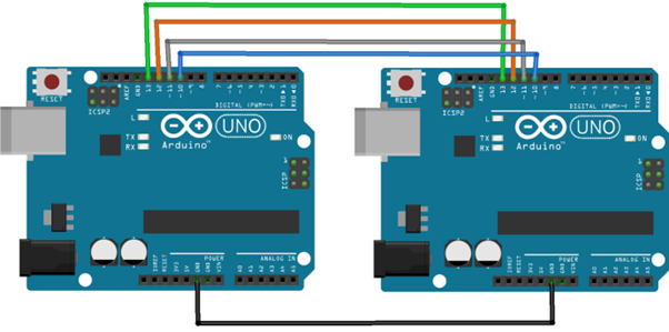
Connect two Arduino boards like shown in below circuit. Make sure to connect both boards to GND and connect all other four SPI pins from pin 10 to 13 of both Arduino.
Hardware
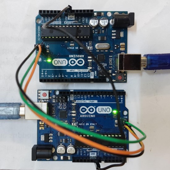
Below is the hardware image of two Arduino boards connected to the PC using the USB cable.
Master Code
#include <SPI.h>/*SPI Library Included*/
void setup() {
Serial.begin(115200); /*Baud Rate defined for Serial Communication*/
digitalWrite(SS, HIGH); /*(SS) Slave Select Line disabled*/
SPI.begin(); /*SPI Communication Begins*/
SPI.setClockDivider(SPI_CLOCK_DIV8); /*Clock divided by 8*/
}
void loop() {
char char_str; /*Variable Defined to send data*/
digitalWrite(SS, LOW); /*(SS)Slave Select Enabled*/
for (const char * p = "LINUXHINT.COM \r" ; char_str = *p; p++) { /*Test String Sent*/
SPI.transfer(char_str); /*SPI transfer begin*/
Serial.print(char_str); /*String is printed*/
}
digitalWrite(SS, HIGH);
delay(2000);
}
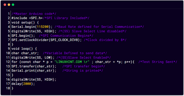
Here in the above code first we included SPI library for communication. Next, we started by defining baud rate to see output on serial monitor slave select line is disabled using digital write. To begin SPI communication SPI.begin() is used.
In loop part of the code a char variable is defined to store the string that we are going to send slave Arduino. Next a string “LINUXHINT.COM” is defined which is transfer to slave Arduino using the SPI.transfer(). To see the input string on the serial-monitor Serial.print() function is used.
Slave Code
#include <SPI.h> /*SPI Library Included*/
char buffer [50]; /*Buffer defined to store received string from Master*/
volatile byte index; /*Save String Data*/
volatile boolean process;
void setup() {
Serial.begin (115200);
pinMode(MISO, OUTPUT); /*MISO set as output to send data to Master*/
SPCR |= _BV(SPE); /*SPI in slave mode active*/
index = 0; /*Buffer empty*/
process = false;
SPI.attachInterrupt(); /*turn on interrupt*/
}
ISR (SPI_STC_vect) { /*SPI interrupt routine*/
byte char_str = SPDR; /*read byte from SPI Data Register*/
if (index < sizeof buffer) {
buffer [index++] = char_str; /*data saved in index of array buff*/
if (char_str == '\r') /*check for string to end*/
process = true;
}
}
void loop(){
if (process) {
process = false; /*Process reset*/
Serial.println (buffer); /*Received array printed on serial monitor*/
index= 0; /*reset button to zero*/
}
}
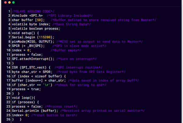
Above code is uploaded to slave Arduino where we started by defining three variables buffer, index and process. Buffer variable will store the input string from the master Arduino while the index will look for the index of elements inside the string and once all the string is printed the process will halt the program and reset to zero. After which again slave will begin receiving data from master Arduino and will be printed on serial monitor.
Output
Output can be seen in two different windows of the Arduino IDE. Output of both master and slave Arduino is printed on serial monitor.
Conclusion
Serial peripheral interface is an important communication protocol used in Arduino programming that helps users to control multiple devices using a single Arduino board. SPI is faster than USART and I2C protocol. It can be implemented in two different configurations single master with single slave or multiple slaves. This article gives an insight how Arduino can be connected for SPI communication.

