Introduction to HC-05 Bluetooth Module
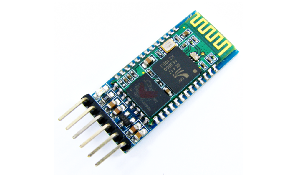
The HC-05 Bluetooth sensor is a wireless communication module that allows devices to communicate with each other using Bluetooth technology. The HC-05 is a slave module, which means it can only be controlled by another device, such as a smartphone or computer, that is acting as the master.
The HC-05 Bluetooth sensor works by using radio frequency (RF) signals to communicate wirelessly with other devices that are equipped with Bluetooth technology. When the HC-05 is powered on and in discovery mode, it sends out a signal that can be detected by other Bluetooth devices in the area.
The HC-05 can operate in a variety of modes, including slave, master, and loopback mode, and can be configured to operate at different baud rates and communication protocols. A password can also be added for advanced security.
In addition to its wireless communication capabilities, the HC-05 also has a built-in voltage regulator and a 3.3V output pin, which can be used to power other sensors.
HC-05 Pinout
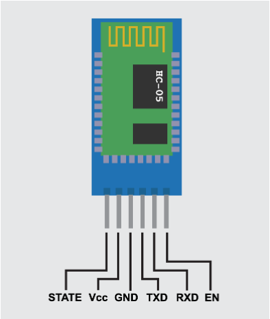
The HC-05 Bluetooth sensor has a total of 6 pins, as follows:
- VCC: This is the power supply pin, which should be connected to a 3.3V/5V power source.
- GND: This is the ground pin, which should be connected to the ground of the power source.
- RXD: This is the receive data pin, that receives data from the master device.
- TXD: This is the transmit data pin, which is used to transmit data to the master device.
- STATE: This is a status pin that can be used to determine the current state of the HC-05, such as whether it is connected or disconnected.
- EN: This is the enable pin, which can be used to enable or disable the HC-05.
In addition to these 6 pins, the HC-05 also has a voltage regulator and a 3.3V output pin.
Interfacing HC-05 with Arduino Nano
To interface the Arduino Nano with an HC-05 Bluetooth sensor, you will need to follow these steps:
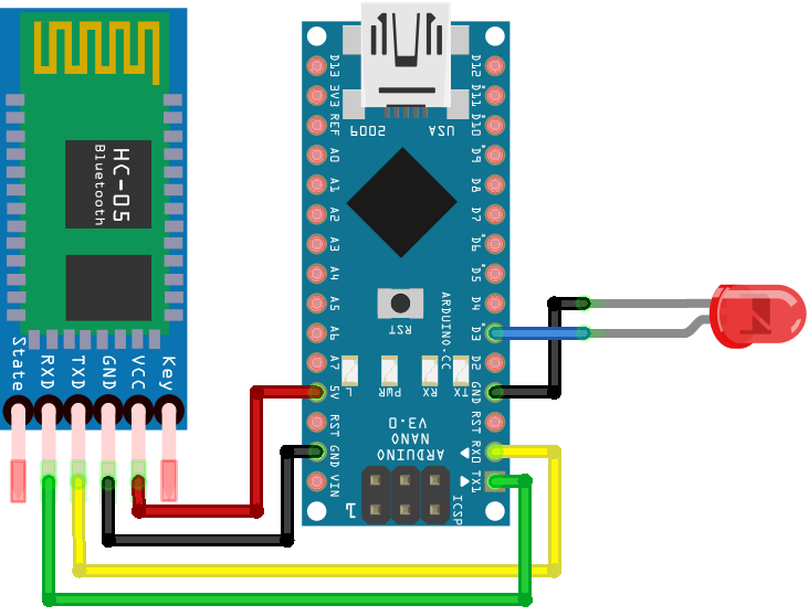
- Connect the HC-05 to the Arduino Nano: Connect the VCC pin of the HC-05 to the 3.3V pin of the Arduino Nano, the GND pin of the HC-05 to the GND pin of the Arduino Nano, the RXD pin of the HC-05 to the TXD pin of the Arduino Nano, and the TXD pin of the HC-05 to the RXD pin of the Arduino Nano.
- Upload the sketch to the Arduino Nano: Use the Arduino IDE to write and upload a sketch to the Arduino Nano. The sketch should include code to initialize the serial communication with the HC-05 and to send and receive data over Bluetooth.
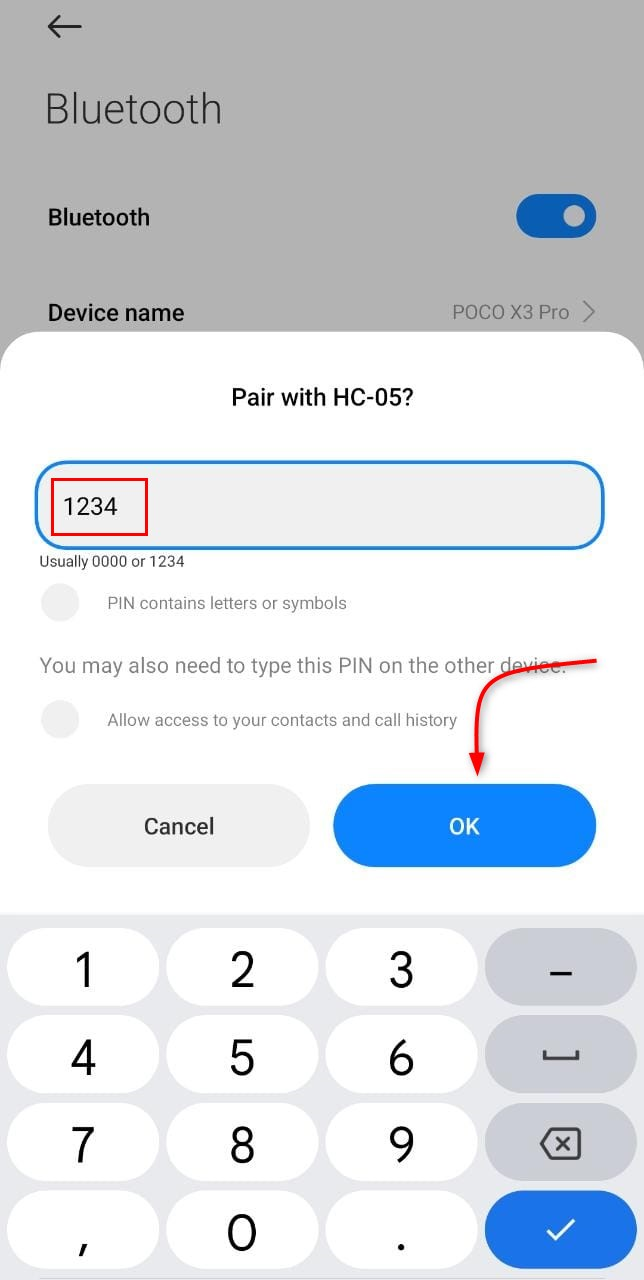
- Pair the HC-05 with a device: Use a device, such as a smartphone or computer, to scan for available Bluetooth devices and pair with the HC-05. For pairing password is required which is usually 1234.
- Test the connection: Once the HC-05 is paired with a device, you can use the Arduino Nano and the HC-05 to send and receive data wirelessly over Bluetooth. The Arduino serial monitor shows the data being transmitted and received.
With these steps, you should be able to successfully interface the Arduino Nano with an HC-05 Bluetooth sensor and use it for wireless communication in your projects.
Schematic
Following image illustrates the connection of the HC-05 sensor with the Arduino Nano. Remember to connect the Tx pin of Arduino Nano with Rx of HC-05 and Rx of Arduino Nano with Tx of Bluetooth sensor.
Note: While uploading code to Arduino Nano remember to remove the Tx and Rx pins. Because if these pins are under use it will block the serial communication between Arduino and PC which will result in failed uploading error.
Code
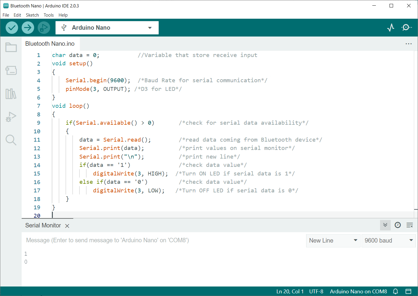
Open the IDE and upload the given code to board.
void setup()
{
Serial.begin(9600); /*Baud Rate for serial communication*/
pinMode(3, OUTPUT); /*D3 for LED*/
}
void loop()
{
if(Serial.available() > 0) /*check for serial data availability*/
{
data = Serial.read(); /*read data coming from Bluetooth device*/
Serial.print(data); /*print values on serial monitor*/
Serial.print("\n"); /*print new line*/
if(data == '1') /*check data value*/
digitalWrite(3, HIGH); /*Turn ON LED if serial data is 1*/
else if(data == '0') /*check data value*/
digitalWrite(3, LOW); /*Turn OFF LED if serial data is 0*/
}
}
Code started by defining the variable that will store the input Bluetooth serial data. Next serial baud rate is defined to show output on the serial monitor. Pin D3 is defined for LED output.
Next code will continuously check for the serial data coming from the Bluetooth sensor if the read serial data is 1 LED will turn ON and if the serial data received is 0 LED will turn OFF.
Controlling LED Using Smartphone and HC-05 Sensor
After uploading code to the Arduino Nano board now we will control an external LED using the smartphone. Follow all the steps to establish communication with your smartphone.
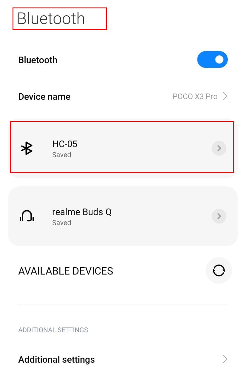
Step 1: Open the Bluetooth settings in your smartphone and search for the new devices. Click the HC-05 device.
Step 2: Pair the HC-05 sensor with a smartphone using the password 1234.
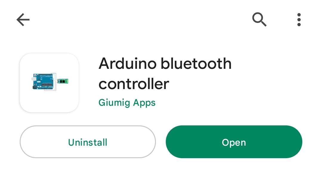
Step 3: Now open the App store on your smartphone and install the Arduino Bluetooth Controller.
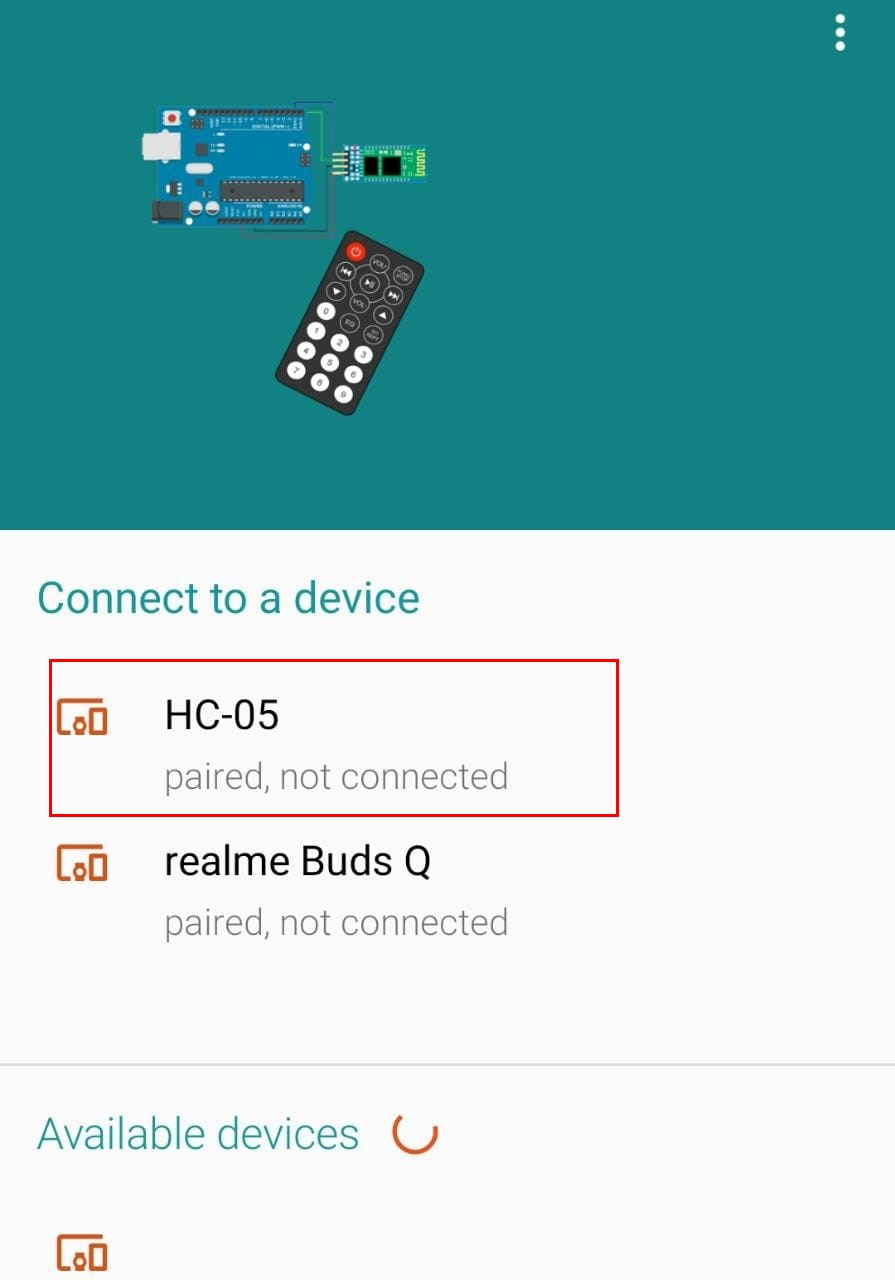
Step 4: Open the application and pair the HC-05 sensor.
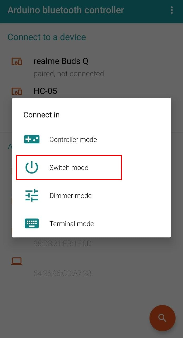
Step 5: Click the HC-05 Bluetooth and select the switch mode.
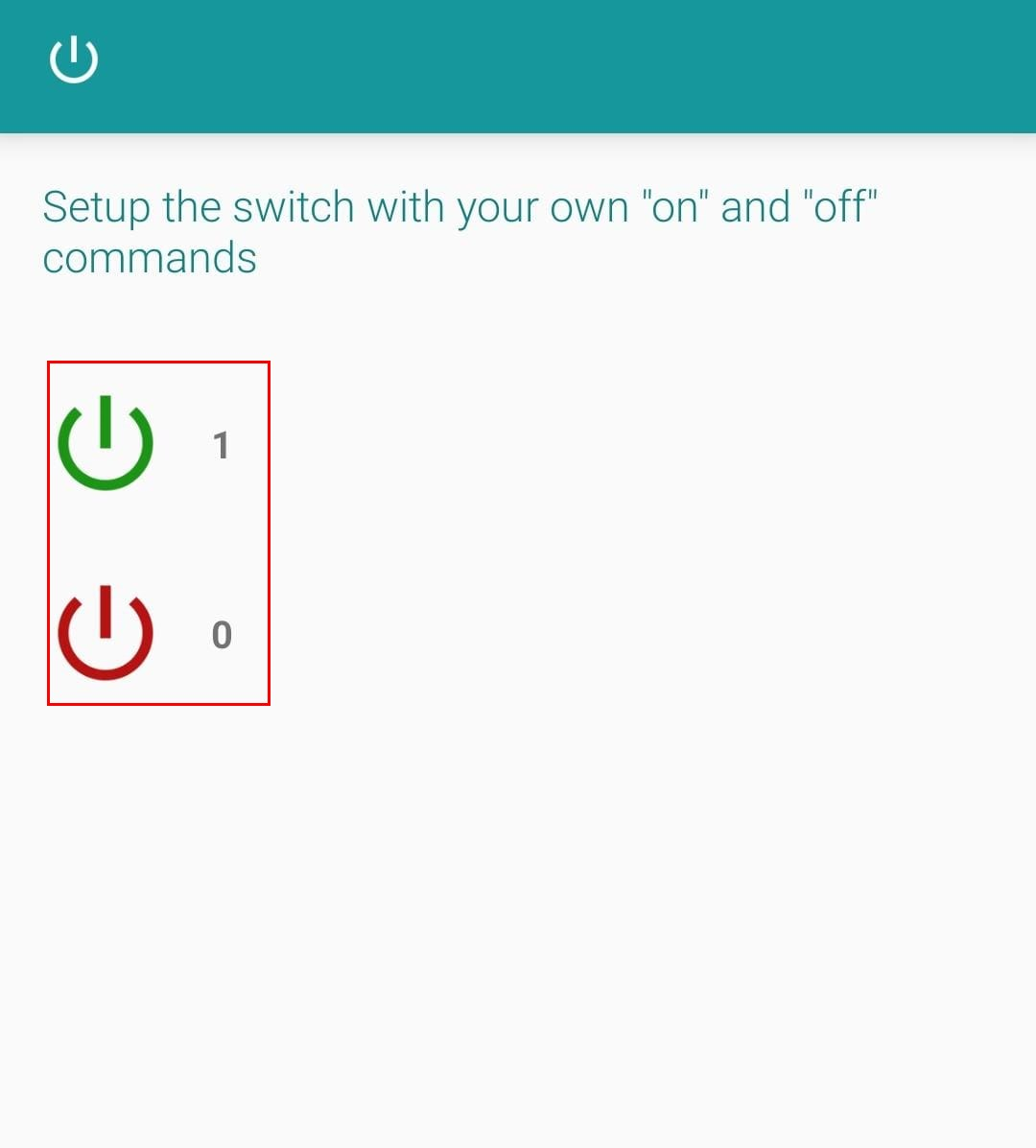
Step 6: Set the values for the switch button. 1 value corresponds to HIGH and 0 is equal to LOW.
We have set up the Bluetooth application on our smartphones. Now we will control LEDs using the smartphone Bluetooth signal.
Output
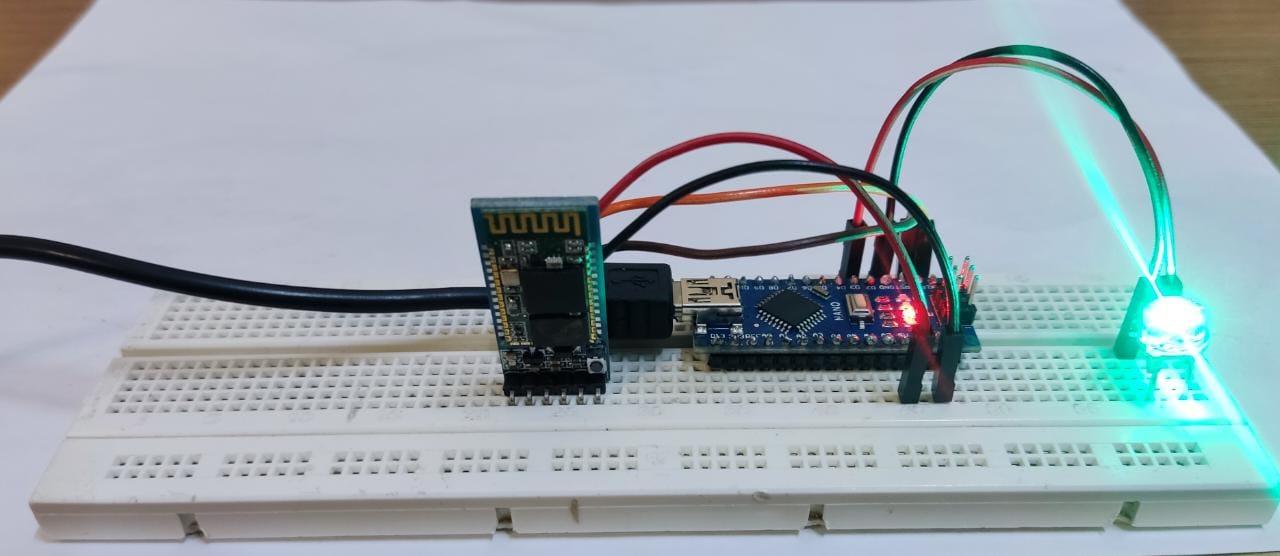
Click the switch button and it will turn green.
External LEDs connected at D3 will turn ON.
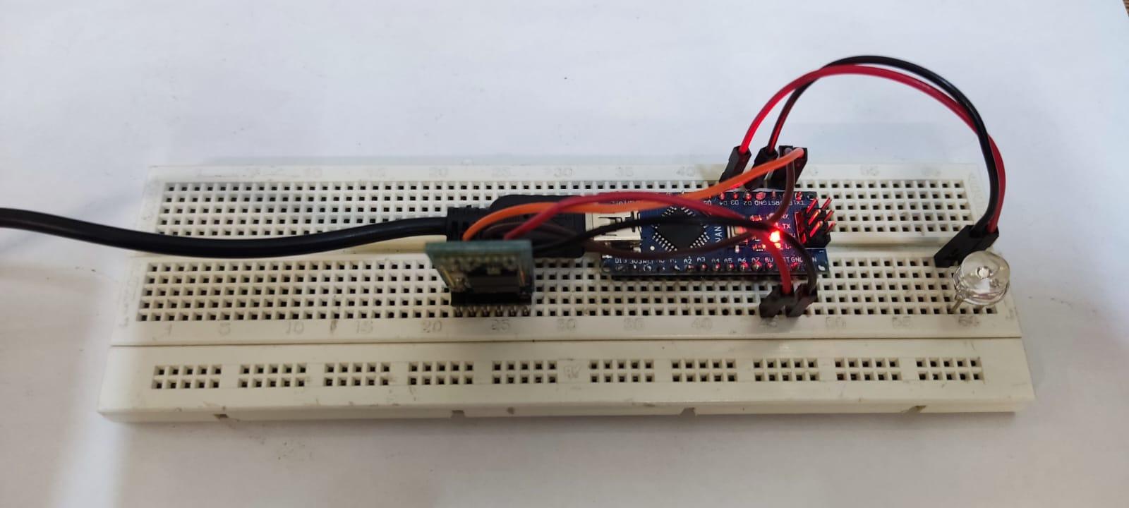
Now again click the button it will turn red. A 0 will be sent to Arduino Nano.
LED will turn OFF because the received serial data is LOW which corresponds to 0.
We have successfully completed interfacing of HC-05 Bluetooth with Arduino Nano and controlled a LED using the serial Bluetooth signal.
Conclusion
HC-05 is a Bluetooth sensor which can be controlled using the Arduino code. This sensor allows control of devices wirelessly over a short range. In this article we interface Arduino Nano with HC-05 and control a LED using the Bluetooth serial signal.

