What is a 7-Segment Display?
The Seven Segment Display or 7-segment display is constructed by using 7 Light Emitting Diodes in an arrangement such that it becomes able to show digits from 0 to 9. Each LED is known as a segment. The LEDs are lit up when their PN Junction is forward-biased by the application of external voltage. The main purpose of using LEDs is that they are very small and are easily joined together to form a compact device such as a 7 Segment Display.
Construction of 7-Segment Display
The Seven Segment Display is made through LEDs by using two kinds of configurations, as explained below:
1. Common Cathode Configuration
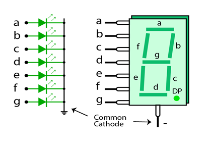
In Common Cathode Configuration, cathodes of all PN junctions of LEDs are joined together and grounded. When the ‘Logic 1’ signal is applied to the anode of individual pins (a-g) of a LED through a resistor that limits current, the respective LED is illuminated.
2. Common Anode Configuration
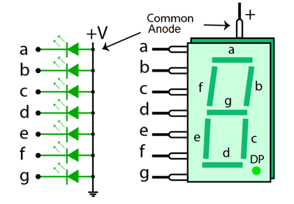
In Common Anode Configuration, anodes of all PN junctions of LEDs are combined and connected to ‘Logic 1’. When the ‘Logic 0’ signal is applied to the anode of individual pins (a-g) of a LED through a resistor that limits current, the respective LED is illuminated. This type is more commonly used.
Working of 7-Segment Display
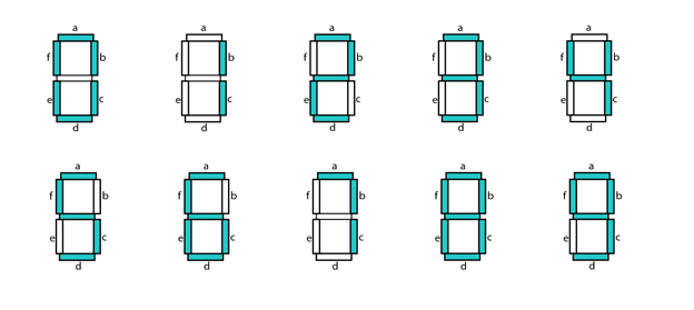
The 7 Segment Display works by illuminating LEDs required to show a certain digit. For displaying 8, it illuminates all LEDs and for displaying 0, the only power to pin ‘g’ is disconnected. For displaying 1, only pins ‘b’ and ‘c’ are given power.
For 2, pin a, b, g, e, and d all are energized, and so on for other digits. The 7-Segment display can also be used to display a decimal point either to the left or right by using an 8th LED when two & Segments are joined together to display numbers greater than 10.
Truth Table of 7-Segment Display
This truth table shows which of the pins are to be activated for displaying respective digits.
| Decimal Digit | Individual Segments Illuminated | ||||||
|---|---|---|---|---|---|---|---|
| a | b | c | d | e | f | g | |
| 0 | 1 | 1 | 1 | 1 | 1 | 1 | 0 |
| 1 | 0 | 1 | 1 | 0 | 0 | 0 | 0 |
| 2 | 1 | 1 | 0 | 1 | 1 | 0 | 1 |
| 3 | 1 | 1 | 1 | 1 | 0 | 0 | 1 |
| 4 | 0 | 1 | 1 | 0 | 0 | 1 | 1 |
| 5 | 1 | 0 | 1 | 1 | 0 | 1 | 1 |
| 6 | 1 | 0 | 1 | 1 | 1 | 1 | 1 |
| 7 | 1 | 1 | 1 | 0 | 0 | 0 | 0 |
| 8 | 1 | 1 | 1 | 1 | 1 | 1 | 1 |
| 9 | 1 | 1 | 1 | 1 | 0 | 1 | 1 |
Pinout Diagram of 7-Segment Display
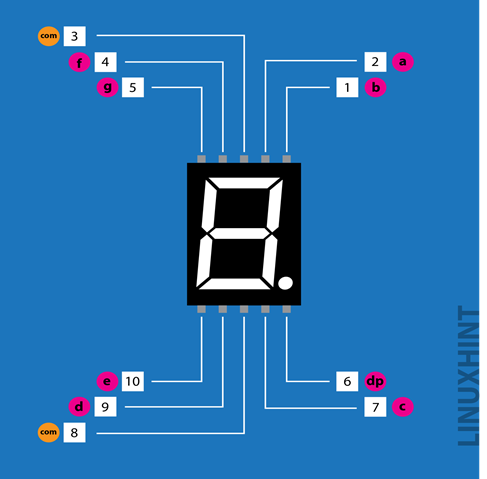
The pinout diagram and specification of each pin of the 7 Segment Display are given below
| Pin Number | Pin Name | Pin Description |
|---|---|---|
| 1 | E | Bottom Left Segment |
| 2 | D | LED at the bottom |
| 3 | Com | Common Ground or Common VCC |
| 4 | C | Bottom Right LED |
| 5 | DP | Decimal Point LED |
| 6 | B | Top Right LED |
| 7 | A | Top Most LED |
| 8 | Com | Common Ground or Common VCC |
| 9 | F | Top Left LED |
| 10 | G | Middle LED |
Interfacing of 7-Segment Display with Arduino
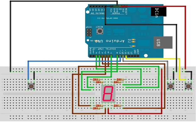
This table will explain to you how would you connect 7 Segment display to your Arduino UNO board
| 7 segment Pins | Arduino Pins |
|---|---|
| 1 (e) | 6 |
| 2 (d) | 5 |
| 3,8 (Com) | GND |
| 4 (c) | 4 |
| 5 (DP) | – |
| 6 (b) | 3 |
| 7 (a) | 2 |
| 9 (f) | 7 |
| 10 (g) | 8 |
Connect the pins as explained above. When the Arduino is energized, the 7-segment display will show digits according to the programmed Arduino.
Applications of 7-Segment Display
The Seven Segment Display has diverse applications in the field of electronics as well as daily life. It is used in digital clocks, wristwatches, calculators, computers, speedometers, radio frequency indicators, and counters. The most prevalent reason for using 7-segment displays in electronic devices is their feature of low power consumption.
Conclusion
The Seven Segment Display is an electronic device made up of multiple LEDs that are arranged in rectangular form, with one in the middle. This device is used to present digits from zero to nine. It operates in two different configurations, i.e. common cathode and common anode. Moreover, It has diverse applications in electronic devices that are used in day-to-day life.

