This article covers:
- 1: Introduction to IR Sensor
- 2: IR Sensor Pinout
- 3: Introduction to Relay
- 4: Relay Pinout
- 5: Interfacing IR Sensor with Arduino
- 5.1: Schematic
- 5.2: Installing the Required Library
- 6: Decoding an IR Remote Buttons
- 6.1: Code
- 6.2: Output
- 7: Controlling an AC Bulb Using IR Remote and Arduino Uno
- 7.1: Schematic
- 7.2: Code
- 7.3: Output
- 8: Designing a Smartphone Based IR Remote for AC Appliances Using Arduino Uno
- Conclusion
1: Introduction to IR Sensor
An IR receiver LED, or Infrared Receiver Light-Emitting Diode, is a device that is used to detect and receive infrared signals. It is commonly used in remote control systems, where it receives signals from a remote control and sends them to a microcontroller or other device for processing.
By using an IR sensor and Arduino, it is possible to create a customized and convenient way to control AC appliances without the need for manual switches or physical buttons, also it can be integrated with other smart home devices for automation.
2: IR Sensor Pinout
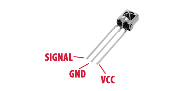
The IR receiver sensor is a small module that typically has three pins:
- VCC
- GND
- OUT
The VCC pin is connected to a power supply, such as the 5V pin on the Arduino, to provide power to the sensor. the GND pin is connected to the ground pin on the Arduino and the OUT pin is connected to a digital input pin on the Arduino:
3: Introduction to Relay
A relay is an electrically operated switch that allows for the control of high-voltage or high-current circuits using a low-voltage signal. When used in conjunction with an Arduino microcontroller, it provides a simple and effective way to control a wide range of devices and appliances.
The Arduino sends a signal to the relay, causing it to open or close a circuit, which in turn controls the power to the connected device. For more details on integration of relay with Arduino read the article Interfacing of Relay with Arduino and ESP32.
A relay contains following control pins:
- NC (Normally Closed)
- COM (Common)
- NO (Normally Open)
Normally Closed: Relays in this configuration are closed by default. Current flows between common and NC in a normal configuration, unless a trigger signal interrupts the current flow.
Common: Control the main current (Supply voltage of external device)
Normally Open: Normally open configuration is opposite to NC as in this mode current does not flow by default, it only flows after a trigger signal is received from Arduino.
4: Relay Pinout
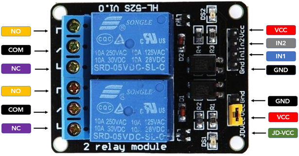
A dual channel relay Pinout is:
| Pin Number | Pin Name | Specification |
|---|---|---|
| 1 | VCC | Relay coil Supply |
| 2 | IN2 | Input for channel 2 |
| 3 | IN1 | Input for channel 1 |
| 4 | GND | GND |
| 5 | NO | Normally Open |
| 6 | Common | COM terminal |
| 7 | NC | Normally Closed |
Note: If you are using a relay with more than one channel then remember to short the JD VCC and VCC pin with a connector (yellow) as shown in above image.
5: Interfacing IR Sensor with Arduino
To use the IR receiver sensor with an Arduino, a library called IRremote is required. This library can be downloaded from the Arduino website and allows the Arduino to decode the IR signals received by the sensor. Once the library is installed, it can be included in the sketch (program) that is uploaded to the Arduino.
Once the IR receiver sensor is connected and the sketch is uploaded, the Arduino can begin to receive and interpret signals from an IR remote control. The IR signals can be decoded using a function provided by the IRremote library, and the decoded signals can then be used to control various devices.
For example, a specific IR signal can be used to turn a device on or off, or to control the brightness or temperature.
5.1: Schematic
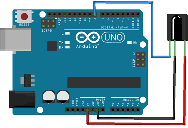
Here is a basic schematic for connecting an IR sensor to an Arduino:
| IR sensor | Arduino |
|---|---|
| VCC (power) | 5V |
| GND (ground) | GND |
| OUT (output) | D8 |
5.2: Installing the Required Library
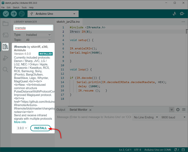
There are several IR remote libraries available for Arduino, you can use any of these libraries as per your requirement and IR remote protocol you are using.
We will install the IRremote library by ArminJo:
6: Decoding an IR Remote Buttons
Before we can control an AC appliance, we must decode the IR remote so we can define that specific HEX value inside the Arduino code. That HEX value corresponds to an IR remote button using which we can turn ON or OFF the appliance.
There are multiple IR remotes available such as for televisions, air conditioners, and home automation systems. By decoding an IR remote we can design a universal remote for all of these appliances.
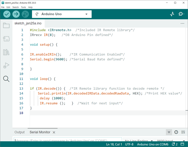
To decode an IR remote, upload the below given code and press the buttons on the IR remote then observe the serial monitor of the Arduino IDE. The example sketch will print the IR signal in HEX format and the protocol used.
6.1: Code
The Arduino Uno board can be programmed by uploading code through the Arduino IDE:
IRrecv IR(8); /*D8 Arduino Pin defined*/
void setup() {
IR.enableIRIn(); /*IR Communication Enabled*/
Serial.begin(9600); /*Serial Baud Rate defined*/
}
void loop() {
if (IR.decode()) { /*IR Remote library function to decode remote */
Serial.println(IR.decodedIRData.decodedRawData, HEX); /*Print HEX value*/
delay (1000);
IR.resume (); } /*Wait for next input*/
}
Code started by including an IR remote library. After that we defined the Arduino digital pin at which the IR signal will be read. Next in the setup() part we initialize the IR communication and baud rate is defined.
In loop() part of code we decode the received IR signal in HEX format which is then printed on serial monitor:
6.2: Output
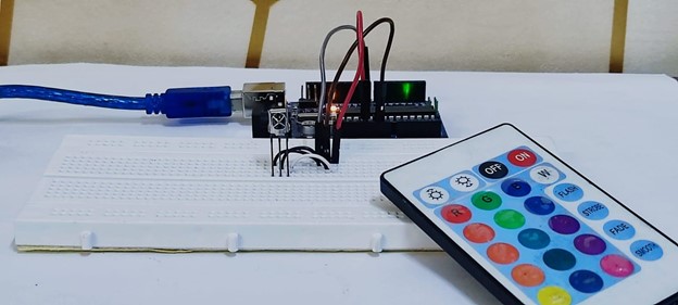
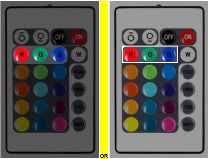
After uploading the code, we pressed three buttons Red, Green and Blue on the IR remote:
Following HEX code is obtained for the red, green and blue button on the IDE serial monitor:
| IR Remote Button | HEX Code |
|---|---|
| RED Button | 0xFB04EF00 |
| GREEN Button | 0xFA05EF00 |
| BLUE Button | 0xF906EF00 |
By defining these HEX codes inside the Arduino program, we can set any of the IR remote buttons as a control for AC appliances and bulbs. Here we will continue with the RED button HEX code.
7: Controlling an AC Bulb Using IR Remote and Arduino Uno
To control a device with the IR remote, you will need to use the decoded HEX signals in your sketch. For example, you can use an if-else statement to check the decoded signal and turn on or off a specific device.
7.1: Schematic
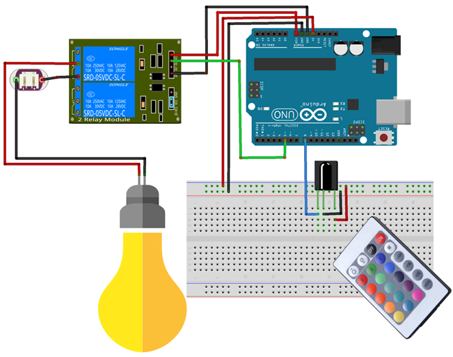
The given image explains the connection of the AC bulb with Arduino and IR receiver:
| AC Bulb & IR Sensor | Arduino Pin |
|---|---|
| Bulb | D5 |
| IR Sensor OUT | D8 |
| Relay Pin | Arduino Pin |
|---|---|
| IN2 | D5 |
| VCC | VIN |
| GND | GND |
| COM | AC (+ive) |
| NC2 | AC (-ive) |
7.2: Code
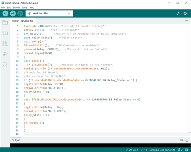
Following is the Arduino code for the IR remote control bulb, the following code can be uploaded to the Arduino Uno board by through the Arduino IDE:
IRrecv IR(8); /*IR Pin defined*/
int Relay=5; /*Relay Pin on Arduino for AC Relay (PIN D5)*/
bool Relay_State=1; /*Relay State*/
void setup() {
IR.enableIRIn(); /*IR Communication enables*/
pinMode(Relay, OUTPUT); /*Relay Pin Set as Output*/
Serial.begin(9600);
}
void loop() {
if (IR.decode()){ /*Decode IR Signal in HEX format*/
Serial.println (IR.decodedIRData.decodedRawData, HEX);
/*Check for IR input*/
/*Relay Code for AC Bulb*/
if (IR.decodedIRData.decodedRawData == 0xFB04EF00 && Relay_State == 1) {
digitalWrite(Relay, HIGH);
Serial.println("Bulb ON");
Relay_State = 0;
}
else if(IR.decodedIRData.decodedRawData == 0xFB04EF00 && Relay_State == 0)
{
digitalWrite(Relay, LOW);
Serial.println("Bulb OFF");
Relay_State = 1;
}
IR.resume ();
}
}
Code started by including an IR remote library. After that we defined the Arduino digital pin at which the IR signal will be read. Next a pin for an AC bulb is defined at D5.
In the setup() part we initialize the IR communication and baud rate is defined. Along with that an AC bulb pin is set as output using pinMode() function.
In loop() part of code if-else condition is used for the AC bulb. You can set any of the IR remote buttons by describing the HEX value inside the code.
| IR Remote Button | HEX Code |
|---|---|
| RED Button | 0xFB04EF00 |
| GREEN Button | 0xFA05EF00 |
| BLUE Button | 0xF906EF00 |
Note: Remember these are the HEX code for the remote one we are using. Your remote may have a different HEX code. So, replace the code with HEX code you got in the serial monitor.
7.3: Output
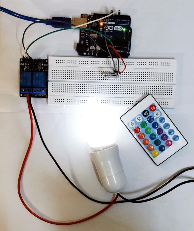
After uploading code to the Arduino board, pressing the red button on the IR remote AC bulb will glow after receiving a signal from the relay:
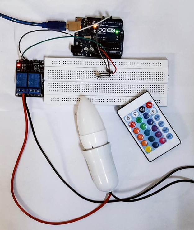
To turn OFF the AC bulb simply press the button again as we have used the toggle condition in Arduino code:
Following is the serial terminal output:
Using the same method any of the AC appliances can be controlled with a Relay switch and an IR remote.
8: Designing a Smartphone Based IR Remote for AC Appliances Using Arduino Uno
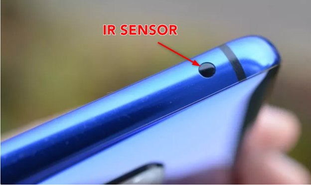
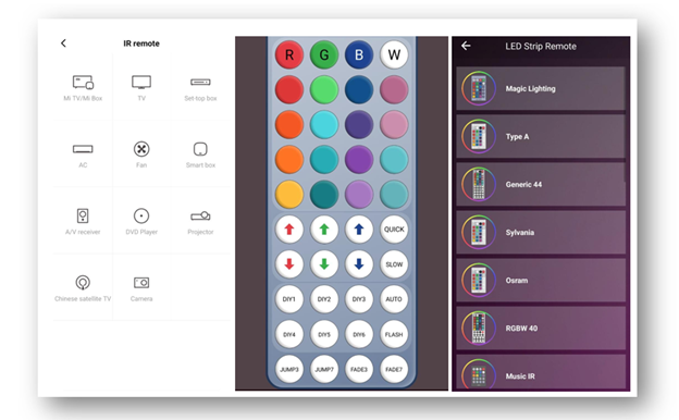
If your smartphone has an IR sensor you can design a custom remote control to control devices and appliances. First, we have to decode the smartphone-based IR remote using Arduino, you will need an IR receiver module and an Arduino board.
Using the above given code we can easily decode any IR remote present in smartphones and can also design a custom one.
Following are some sample images of IR remote present in smartphones:
Conclusion
In summary, decoding an IR remote control with an Arduino microcontroller is a simple and cost-effective way to control various devices. By connecting an IR receiver to the Arduino, uploading a sketch, and decoding the IR signals, you can easily control AC appliances and devices such as televisions, air conditioners, and home automation systems.

